Service Life: Service Life of Gearheads
The gearhead life is reached mainly when power can no longer be transmitted because the bearing mechanical life has ended. Therefore, the actual life of a gearhead varies depending on the load, how the load is applied, and the rotation speed used. Oriental Motor defines life under certain conditions as rated life, based on which the life under actual operation is calculated according to load conditions and other factors. The tooth surface of Oriental Motor's gearheads is lubricated by a grease lubrication mechanism. Lubrication is not required.
Rated Life of Parallel Shaft and Right-Angle Shaft Types
The rated life of parallel shaft and right-angle shaft types is determined by the load applied to the bearing by the transmission torque and the load applied to the bearing by the radial and axial loads on the output shaft.
Oriental Motor defines the rated life as the life of a gearhead under the following operating conditions:
Conditions
- Torque
- Permissible torque
- Load Type
- Uniform load
- Input Rotation Speed
- Reference input rotation speed
- Radial Load
- Permissible radial load
- Axial Load
- Permissible axial load
Table 1: Rated Life Time of Parallel Shaft and Right-Angle Shaft Types
| Motor Type | Series | Gearhead Type | Reference Input Rotation Speed [r/min] |
Rated Life [Hours] |
|---|---|---|---|---|
| AC Motors | KIIS Series KII Series |
Parallel Shaft Gearhead | 1500 | 10000 |
| Right-Angle Hollow Shaft Hypoid GV Gearhead | ||||
| JH Gearhead, JL Gearhead | 5000 | |||
| BH Series | Parallel Shaft Gearhead | 5000 | ||
| Right-Angle Gearhead | 10000 | |||
| World K Series K Series |
Parallel Shaft Gearhead | 5000 | ||
| Right-Angle Gearhead | ||||
| TM Series | Parallel Shaft Gearhead | 10000 | ||
| Torque Motors SMK Series |
Parallel Shaft Gearhead | 5000 | ||
| FPW Series | Parallel Shaft Gearhead | 5000 | ||
| AC Speed Control Motors |
US2 Series DSC Series |
Parallel Shaft Gearhead | 10000 | |
| JH Gearhead, JL Gearhead | 5000 | |||
| US Series | Parallel Shaft Gearhead | 5000 | ||
| Right-Angle Gearhead | ||||
| Brushless Motors | BMU Series BLE2 Series |
Parallel Shaft Gearhead | 3000 | 10000 |
| Parallel Shaft Gearhead H1 Food-Grade Lubricant |
5000 | |||
| Hollow Shaft Flat Gearhead | 10000 | |||
| JH Gearhead, JB Gearhead, JV Gearhead | 5000 | |||
| BXII Series BLE Series BLV Series |
Parallel Shaft Gearhead | 10000 | ||
| Hollow Shaft Flat Gearhead | ||||
| BLH Series | Parallel Shaft Gearhead* | 10000 | ||
| CS Geared Type | ||||
| Hollow Shaft Flat Gearhead | ||||
| αSTEP/ Stepper Motors |
AZ Series RKII Series |
TS Geared Type | 1500 | 10000 |
| FC Geared Type | 5000 | |||
| AR Series | TH Geared Type | 5000 | ||
| FC Geared Type | ||||
| CRK Series | TH Geared Type | 5000 | ||
| 2-Phase PK Series | SH Geared Type (□90 mm) |
5000 | ||
| 2-Phase PKP Series | SH Geared Type | 10000 | ||
| CS Geared Type | ||||
| 5-Phase PKP Series | TS Geared Type | 10000 |
- *15 W has a rated life of 5000 [hours].
Planetary Geared Type Rated Life
The rated life of the planetary geared type is determined by the load applied to the bearing due to the radial or axial load applied to the output shaft.
Oriental Motor defines the rated life as the life of a gearhead under the following operating conditions:
Conditions
- Torque
- Permissible torque
- Load Type
- Uniform load
- Input Rotation Speed
- Reference input rotation speed
- Radial Load
- Permissible radial load
- Axial Load
- Permissible axial load
- *Value when either radial load or axial load is applied
Table 2: Rated Life Time of Planetary Geared Type
| Motor Type | Series | Gearhead Type | Reference input rotation speed [r/min] |
Rated Life [Hours] |
|---|---|---|---|---|
| αSTEP/ Stepper Motors |
AZ Series RKII Series |
PS Geared Type | 1500 | 20000 |
| AR Series CRK Series |
PS Geared Type | 20000 | ||
| PN Geared Type | ||||
| Servo Motors | AZX Series NX Series |
PS Geared Type | 3000 | 10000 |
Rated Life of Harmonic Geared Type and HPG Geared Type
The rated life of the harmonic geared type and the HPG geared type is determined by the load applied to the gears and bearings by the transmission torque, and the load applied to the bearings due to the radial and axial load applied to the output shaft.
Oriental Motor defines the rated life as the life of a gearhead under the following operating conditions:
Conditions
- Torque
- Permissible torque
- Load Type
- Uniform load
- Input Rotation Speed
- Reference input rotation speed
- Radial Load
- Permissible radial load
- Axial Load
- Permissible axial load
- *The HPG geared type represents the value when either radial load or axial load is applied
Table 3: Rated Life Time of Harmonic Geared Type and HPG Geared Type
| Motor Type | Series | Gearhead Type | Reference input rotation speed [r/min] |
Rated Life [Hours] |
|---|---|---|---|---|
| αSTEP/ Stepper Motors |
AZ Series | HPG Geared Type | 1500 | 20000 |
| Harmonic Geared Type (□30 mm, □42 mm) |
7000 | |||
| Harmonic Geared Type (□60 mm、□90 mm) |
10000 | |||
| AR Series CRK Series |
Harmonic Geared Type | 5000 | ||
| RKII Series | Harmonic Geared Type (□42 mm) |
7000 | ||
| Harmonic Geared Type (□60 mm、□90 mm) |
10000 | |||
| 2-Phase PKP Series | With flat harmonic gearhead (□51 mm) |
5000 | ||
| With flat harmonic gearhead (□61 mm) |
7000 |
Estimating Lifetime
Lifetime under actual conditions of use is calculated based on the rotation speed, load and load type, using the following formula. The calculated lifetime represents the actual driven hours.
- L1
- Rated life time [hours]
Determined by each gearhead type from Table 1~3.
- K1
-
Rotation speed coefficient
The speed coefficient K1 is calculated based on the reference input rotation speed listed in Table 1~3 and the actual input rotation speed.\(\begin{align}K_1=\frac{\text{Reference input rotation speed}}{\text{Actual Input Rotation Speed}}\end{align}\)
- K2
-
Load factor
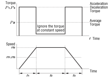
The load factor K2 is calculated based on the actual operating torque and the permissible torque for each gearhead.\(\begin{align}K_2=\frac{\text{Operating Torque}}{\text{Permissible torque}}\end{align}\)The average torque may be considered operating torque if the gearhead is subject to load while starting and stopping only, such as when driving an inertial load. For the calculation method, refer to How to Obtain the Average Torque. Permissible torque represents the specification values listed in the product catalog.
- f
- Load-Type Coefficient f
The load-type coefficient f is determined based on load type, using the following drive examples as a reference:
| Load Type | Example | Load-Type Coefficient f |
|---|---|---|
| Uniform Load |
|
1.0 |
| Slight Impact |
|
1.5 |
| Medium Impact |
|
2.0 |
Note
Regarding the Effects of Radial Load and Axial Load
- The above estimated lifetime is calculated according to the radial load and axial load, which are in proportion to a given load factor. For example, if the load factor is 50 %, the life is calculated using 50 % radial load and axial load.
- The actual life of a gearhead having a low load factor and a large radial load or axial load will be shorter than the value determined through the previous formula.
How to Obtain the Average Torque
The stepper motor or servo motor is used for intermittent operation of an inertial load, such as driving an index table and arm. In this case, the average torque shall be considered the operating torque, as described below. The load factor for driving an inertial load using an AC motor or brushless motor shall be 1.0.
Driving an Inertia Body Only ①
The graph below shows torque generated when driving only an inertial load over a long operating cycle. Frictional load caused by bearings and other parts during constant speed operation is negligible and therefore omitted.

n1 and n3 represent the average rotation speed in the t1 and t3 area.
In the above example: \(\begin{align}n_1= n_3 =\frac{1}{2}n_2\end{align}\)
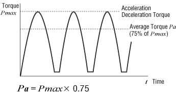
Driving an Inertia Body Only ②: Driving an arm or similar object
When driving an arm or similar object, the gearhead may be subjected to load fluctuation as shown in the following graph. For example, such load fluctuation will occur when driving a double-joint arm or moving an arm in the vertical direction. In such an application, the average torque shall be 75 % of the max. acceleration/deceleration torque, as shown in the following formula.

Operating Temperature
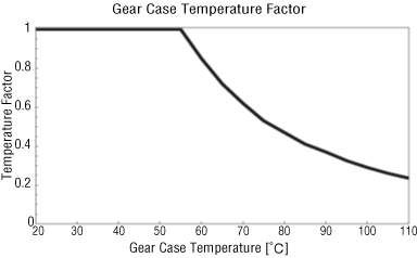
An increase in gearhead temperature affects the lubrication of the bearing.
However, the effect of temperature on gearhead life varies according to the condition of the load applied to the gearhead bearings, frame size and many other factors. This makes it difficult to include temperature effects in the formula to estimate the lifetime.
The following data shows the temperature effect on the gearhead bearings. The gearhead life is affected when the gear case's surface temperature is 55 °C min.

Note
In some cases, a lifetime of several tens of thousands of hours may be obtained from the calculation under certain conditions. Use the estimated life as a reference only.
The above life estimation is based on the bearing life.
An application in excess of the specification values may adversely affect parts other than the bearings. Use the product within the range of specified values listed in the product catalog.