2-Phase Stepper Motors
PKP/PK Series
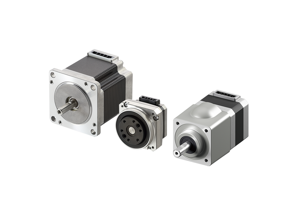
- High torque, low vibration
- Frame Size: 13 to 90 mm
- Geared type, with encoder, and with electromagnetic brake available
Features | 2-Phase Stepper Motor PKP/PK Series
Improved Performance
Higher Torque
Higher current is now possible due to a review of the motor winding design. Increased torque over the entire speed range from low to high is achieved.
Comparison of Speed - Torque Characteristics of the Same Size Motors

Comparison of Maximum Holding Torque

Energy and Power Saving
By reducing the operating current supplied to the motor, the same torque as conventional products can be obtained while reducing power consumption and CO2 emissions.
Power consumption and CO2 emissions are reduced by 56 % compared to the conventional products(compared to our products)

| Rotation Speed | 0.1 kHz (30 r/min) |
|---|---|
| Operating Time | 24 hours a day, 365 days a year |
| Operating Conditions | 50 % in operation, 50 % on standby |
| Power Supply Voltage | 24 VDC |
| CO2 Coefficient | 0.519 kg-CO2/kWh |
Low vibration
Revising the magnetic design has achieved lower vibration than with conventional products.

Save Resources Through Downsizing
Torque improved considerably compared to conventional products. When compared at equivalent torque, using the PKP Series enables motor downsizing. This helps to save space and reduce the weight of the equipment.
44 % reduction in volume when comparing dimensions!

| Product Name | PK264-02A | PKP244U12A2 |
|---|---|---|
| Maximum Holding Torque (N·m) |
0.39 | 0.39 |
| Frame Size (mm) |
56.4 | 42 |
| Mass (kg) | 0.45 | 0.3 |
Compact and Flat Connector
The PKP Series uses a compact and flat connector, which lowers the connector's overhang (excluding some products). In addition, flexibility for the motor cable outlet direction has been increased, as outlet direction points upward.
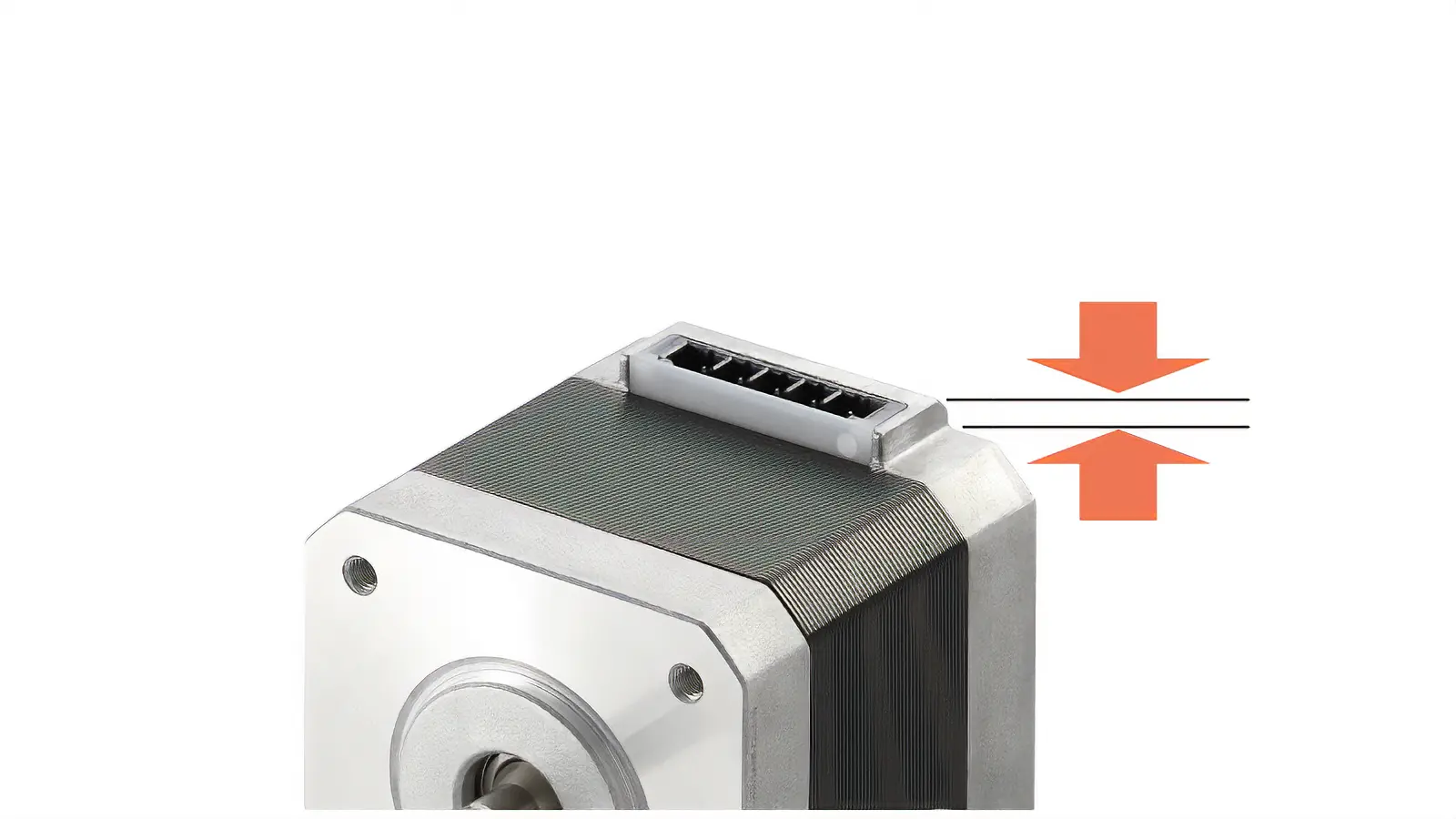
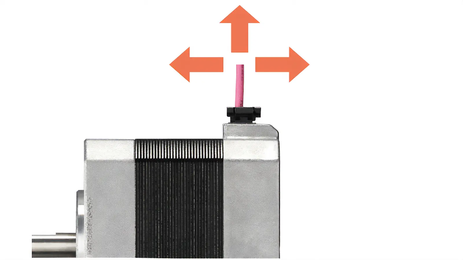
- *For details, refer to the dimensions diagram of each motor.
With Encoder
Models equipped with an encoder are available. Comparing the command position and current position enables you to check the normal operation of the motor.
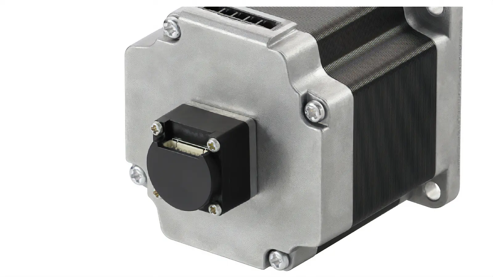
Encoder’s Main Specifications
| Type | Standard Type | High-Resolution Type SH Geared Type |
|---|---|---|
| Resolution | 200 P/R, 400 P/R 1000 P/R* |
400P/R |
| Angular Accuracy | ±0.36° (converted value at motor output shaft) | |
| Output Signals | Phase A, Phase B, Phase Z (3ch) | |
- *The standard types with a frame size of 42 mm and 56.4 mm are also available with a resolution of 1000 P/R.
Angle Accuracy
This is the calculation error between the actual rotation angle and the angle output from the encoder.

Motor Position Detection is Possible
Monitoring the current position and detecting positional errors are possible.
For example, comparing the command position and current position enables you to check the normal operation of the motor.
System Configuration Example

- *Converted value at motor output shaft
Enables Highly Repeatable Return-to-Home Functioning
Since the Z-phase signal is output at the step "0" position (stability point), it can be a substitute for the home sensor (a sensor attached to the motor shaft that detects the home within one revolution).
It also makes it easier to use the Z-phase output signal and TIM output signal* together and improves the repeatability of the return-to-home function.
- *This is the signal output from the driver each time the motor output shaft rotates 7.2° (3.6° for high-resolution types) from the home position.
When the Timing of Z-phase Output is Fixed
New Encoder (Magnetic type)

It outputs Z-phase signals with a width of ±3.6° centered on the step "0" position (stability point).


When the Timing of Z-phase Output is not Fixed

Since the output timing of the Z-phase signal is not fixed, it is difficult to use it as a substitute for the home sensor, and it is also difficult to use it together with the TIM signal.
Compact Encoder Equipped
When the frame size is 56.4 mm
- *The orange area in the dimensions diagram is the encoder section.

Choose Between Voltage Output Type and Line Driver Output Type
A voltage output type and line driver output type are available.
A useful cable for wiring the encoder is also available separately.
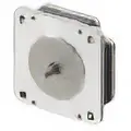
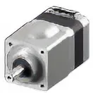
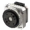
Motor Types
| Classification | Type | Frame Size [mm] |
Basic Step Angle [°] |
Wiring Method | Additional Function |
|---|---|---|---|---|---|
| No Gearhead |

|
13~85 | 1.8 | Bipolar, unipolar |
Encoder, electromagnetic brake |

|
28~56.4 | 0.9 | Bipolar, Unipolar |
Encoder, Electromagnetic Brake |
|
|
42, 60 | 1.8 | Bipolar | None | |
| With Gearhead |

|
28~90 | 0.05~0.5 | Bipolar, Unipolar |
Encoder |
|
28~60 | 0.09~0.36 | Bipolar, Unipolar |
None | |
|
51, 61 | 0.018~0.036 | Bipolar | None |
Related Products
Combined Drivers (Sold separately)
Drivers for 2-phase stepper motors are also available.
Bipolar Driver
CVD Series Pulse Input Type/RS-485 Communication Type
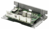
Right-Angle Type With Mounting Plate
The connector points outward.
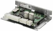
With Mounting Plate
The connector points upward.
Without Mounting Plate
The connector points upward.
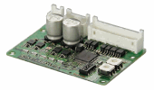
- *The photo shows the pulse input type. The RS-485 communication type is not available without a mounting plate.
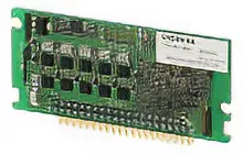
Bipolar Driver
CVD Series S Type
Board type compact drivers are available, one to control motor positioning via SPI communication and the other to control by pulse input.
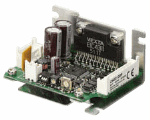
Unipolar Driver
Introduction to Stepper Motor and Driver Combinations
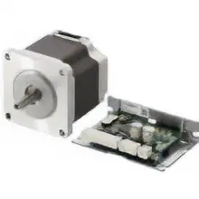
Stepper Motors PKP Series/CVD Series Pulse Input Driver
You want to operate a stepper motor easily by pulse input. This is a motor and pulse input driver that meets such needs. In pursuit of high efficiency, high torque, and low vibration, even better performance has been achieved.
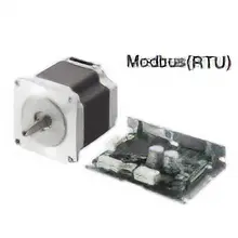
Stepper Motors PKP Series/CVD Series RS-485 Communication Type Driver
You want to run a stepper motor under Modbus (RTU) control. You want set data easily on a touch screen. This product combines a motor with a driver that supports RS-485 communication compatible to meet such needs. Up to 31 axes of drivers can be controlled by connecting them to a single host control device.
Narrow down Products


