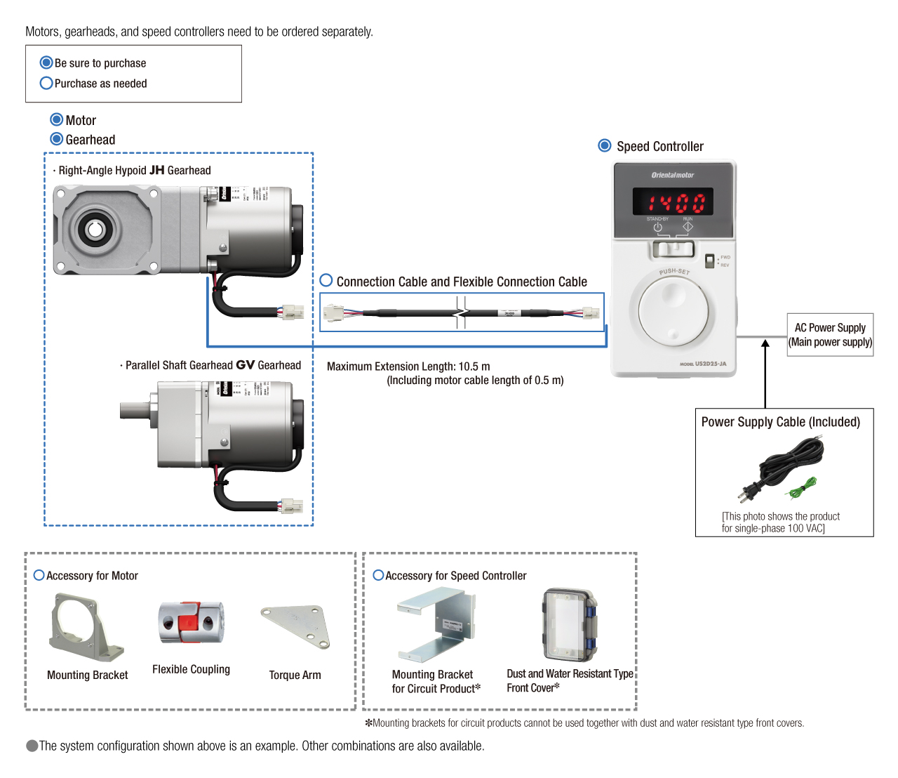
AC Speed Control Motors US2 Series
SCM540KUA+5L30B+US2D40-UA

| Product Classification | Product Name | List Price | List Price | Shipping Date |
|---|---|---|---|---|
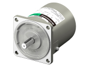
| Motor | SCM540KUA | SGD 136 | USD 109 | 16 Working Days |
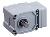
| Gearhead | 5L30B | SGD 236 | USD 189 | 16 Working Days |
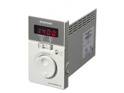
| Control Circuit | US2D40-UA | SGD 176 | USD 141 | 11 Working Days |
Included
- Motor: None
Gearhead: Mounting Screws, Parallel Key
Control Circuit: None
Specifications
Characteristics
Speed - Torque Characteristics
Dimensions
Motor/Gearhead
Control Circuit
Connection Cable (When Selected)
Data Download
Other Specifications
Common Specifications
| Item | Specifications | |
|---|---|---|
| Speed Setting Methods |
Digital setting with dial (speed setting is available by units of 1 r/min) |
|
| Variable Speed Range |
50 Hz: 90~1400 r/min 60 Hz: 90~1600 r/min |
|
| Acceleration Time and Deceleration Time | 0.1~15.0 seconds (Initial Setting: 1.0 second) Acceleration time/deceleration time varies with the load condition of the motor. |
|
| Function | Parameters | Gear ratio, speed increasing ratio, fixed last digit display, prevention of operation at power-on alarm, speed upper/lower limit, acceleration/deceleration time, external operation signal input, data initialization |
| Monitor | Rotation speed, input signal | |
| Other | Lock data editing | |
| Input Signals | Photocoupler Input Input resistance: 2 kΩ FWD Input, REV Input 2 points |
|
| Protective Function | The motor will make a coasting stop and the alarm code will be displayed on the operation panel when the following protective functions are activated. Alarm Types: Motor overheat, Motor lock, poor motor connection, EEPROM error, prevention of operation at power-on |
|
| Maximum Extension Distance | Between motor and speed controller 10 m | |
General Specifications
| Item | Motor | Speed Controller | |
|---|---|---|---|
| Insulation Resistance | 100 MΩ or more when a 500 VDC megger is applied between the windings and the case after continuous operation under normal ambient temperature and humidity. |
Measurement value of 100 MΩ min. when a 500 VDC megger is applied between the main circuit terminal and the input signal terminal, between the main circuit terminal and the case, and between the main circuit terminal and FG after continuous operation under normal ambient temperature and humidity. |
|
| Dielectric Strength | No abnormality is observed when 1.5 kVAC at 50 Hz or 60 Hz applied between the coils and case for 1 minute after continuous operation under normal ambient temperature and humidity. |
No abnormality is observed when 1.9 kVAC at 50 Hz or 60 Hz applied between the main circuit terminal and the input signal terminal and between the main circuit terminal and the case, and 1.5 kVAC at 50 Hz or 60 Hz applied between the main circuit terminal and FG for 1 minute after continuous operation under normal ambient temperature and humidity. |
|
| Temperature Rise | A gearhead or equivalent heat sink *1 is connected to the motor, and the winding temperature rise is measured at 80 °C max. using the resistance change method after continuous operation with no load under normal ambient temperature and humidity. |
- | |
| Overheat Protective Device | 6W Type: Impedance protected All other motors have a built-in thermal protector (automatic return type) Open: 130±5 °C, Return: 85±20 °C |
- | |
| Operating Environment | Ambient Temperature | Single-Phase 100 V, Single-Phase 200 V: -10~+50°C (Non-freezing) Single-Phase 110/115 V, Single-Phase 220/230 V: -10~+40°C (Non-freezing) For gearhead gear ratios 2 or 3 the lower temperature limit is 0°C. Right-Angle Hypoid Gearhead: 0~+40°C (Non-freezing) |
0~+50 °C (Non-freezing) |
| Ambient Humidity | 85 % max. (Non-condensing) | ||
| Altitude | Up to 1000 m above sea level | ||
| Atmosphere | No corrosive gases or dust. Should not be exposed to water or oil. Cannot be used in a radioactive area, magnetic field, vacuum, or other special environments. |
||
| Vibration | Must not be subjected to continuous vibration or excessive shock. Conforms to JIS C 60068-2-6, "Sine-Wave Vibration Test Method." Frequency Range: 10~55 Hz, Half Amplitude: 0.15 mm Sweep direction: 3 directions (X, Y, Z) Number of sweeps: 20 |
||
| Storage Conditions*2 | Ambient Temperature | -25~+70°C (Non-freezing) Right-Angle Hypoid Gearhead: -10~+60°C (Non-freezing) |
-25~+70°C (Non-freezing) |
| Ambient Humidity | 85 % max. (Non-condensing) | ||
| Altitude | Up to 3000 m above sea level Right-Angle Hypoid Gearhead: Up to 1000 m above sea level |
||
| Atmosphere | No corrosive gases or dust. Should not be exposed to water or oil. Cannot be used in a radioactive area, magnetic field, vacuum, or other special environments. |
||
| Thermal Class | 130(B) | - | |
| Degree of Protection | IP20 | IP20 | |
- *1
- The size of the heat sink (Material: aluminum) is shown in the table below.
- *2
- The value for storage condition applies to short periods such as the period during transport.
| Motor Output Power | Size (mm) | Thickness (mm) |
|---|---|---|
| 6 W | 115x115 | 5 |
| 15 W | 125x125 | |
| 25 W | 135x135 | |
| 40 W | 165x165 | |
| 60 W | 200x200 | |
| 90 W | 200x200 |
Note
- Do not measure insulation resistance or perform a dielectric strength test while the motor and speed controller are connected.
Permissible Radial Load and Permissible Axial Load of Gearhead
| Gear Ratio | 10 | 15 | 20 | 30 | 50 | 100 | 200 | ||
|---|---|---|---|---|---|---|---|---|---|
| Permissible Radial Load [N] *1 | Hollow Shaft*2 | 10 mm From Mounting Surface | 415 | 554 | 692 | 923 | 1112 | 1196 | 1291 |
| 20 mm From Mounting Surface | 363 | 484 | 605 | 806 | 971 | 1045 | 1127 | ||
| Solid Shaft | 10 mm From the End of the Output Shaft | 378 | 504 | 630 | 840 | 1011 | 1089 | 1174 | |
| 20 mm From the End of the Output Shaft | 481 | 641 | 802 | 1069 | 1287 | 1385 | 1495 | ||
| Permissible Axial Load [N] | 108 | 147 | 186 | 245 | 294 | 324 | 343 | ||
- *1
- The load position is shown below.
- *2
- For calculations of the radial load from every distance for the hollow shaft type, refer to "Permissible radial load calculation for hollow shaft type" below.
Calculating the Permissible Radial Load for Hollow Shaft Type
The formula for calculating the permissible radial load varies depending on the mechanism.
Standards
Regulations and Standards Materials
Documents about compliance with regulations and standards can be downloaded from the "Data Download" tab on the product details page.
(The types of files available for download vary by product.)
Explanations of the Global Laws, Regulations and Standards can be found here.
Information about our compliance with safety standards for each of our product models can be found here.
Hazardous Substances
The product does not contain any substances (10 substances) exceeding the regulation values of the RoHS Directive (2011/65/EU, 2015/863/EU).
System Configuration