Stepper Motors RKII Series
PKE596MC-HS50
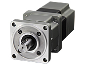
Geared Motor


| Product Classification | Product Name | List Price | List Price | Shipping Date |
|---|---|---|---|---|
| Geared Motor | PKE596MC-HS50 | SGD 1,810 | USD 1,448 | 16 Working Days |
• Specifications and various data of combination products may be shown on the combination product page. Please check the page of the combination product.
Included
- Motor: Parallel Key
Specifications
Characteristics
Characteristics Diagram
Dimensions
Motor
Data Download
Other Specifications
General Specifications
| Motor | Driver | |||
|---|---|---|---|---|
| Built-in Controller Type | Pulse input type | |||
| Thermal Class | 130 (B) [UL is 105 (A) certified] |
− | ||
| Insulation Resistance |
100 MΩ or more when a 500 VDC megger is applied between the following places.
|
100 MΩ or more when a 500 VDC megger is applied between the following places.
|
||
| Dielectric Strength |
Sufficient to withstand the following for 1 minute:
|
Sufficient to withstand the following for 1 minute: | ||
|
|
|||
| Operating Environment (when operating) |
Ambient Temperature |
-10~+50 °C (Non-freezing): Standard Type TS/PS/FC geared type 0~+50 °C (Non-freezing): With encoder 0~+40 °C (Non-freezing): Harmonic Geared Type According to Oriental Motor’s measurement conditions |
0~+55 °C*2 (Non-freezing) | |
| Ambient Humidity | 85 % max. (Non-condensing) | |||
| Atmosphere | No corrosive gases or dust. No exposure to water, oil or other liquids. | |||
| Temperature Rise | 5-phase excitation at rated current, 80 °C max. at standstill Temperature rise of winding section at 80 °C or less (resistance change method) |
− | ||
| Degree of Protection | IP20 | IP10 | IP20 | |
| Stop position accuracy*3 | ±3 arc minute (±0.05˚) | |||
| Shaft Runout | 0.05 T.I.R. (mm)*4 | − | ||
| Radial Play*5 | 0.025 mm Max. (Load 5 N) | − | ||
| Axial Play*6 | 0.075 mm Max. (Load 10 N) | − | ||
| Concentricity of Installation Pilot to the Shaft |
0.075 T.I.R. (mm)*4 | − | ||
| Perpendicularity of mounting surface to the shaft |
0.075 T.I.R. (mm)*4 | − | ||
- *1
- (Only for types with electromagnetic brake)
- *2
- When a heat sink of a capacity at least equivalent to an aluminum plate with a size of 200×200 mm and 2 mm thickness
- *3
- 0.72˚ is the value under no load. (The value changes with the size of the load.)
- *4
- T.I.R. (Total Indicator Reading): The total dial gauge reading when the measurement section is rotated 1 revolution centered on the reference axis center.
- *5
- Radial Play: Displacement in shaft position in the radial direction when a 5 N load is applied perpendicular to the tip of the motor shaft.
- *6
- Axial Play: Displacement in shaft position in the axial direction when a 10 N load is applied to the motor shaft in the axial direction.
Note
- Disconnect the motor and driver when measuring insulation resistance, or conducting a dielectric strength test.
Electromagnetic Brake Specifications
| Product Name | PKE54 | PKE56 | PKE59 |
|---|---|---|---|
| Type | Power off activated type | ||
| Power Supply Voltage | 24 VDC ±5 %* | ||
| Power Supply Current [A] | 0.08 | 0.25 | 0.42 |
| Time Rating | Continuous | ||
- *For the type with an electromagnetic brake, a 24 VDC ±4 % specification applies if the wiring distance between the motor and the driver is extended by 15 m using a cable.
- The product names are listed such that the product names are distinguishable.
Encoder Specifications
| Resolution | 500P/R |
|---|---|
| Output Mode | Incremental |
| Output Signals | 3 channels |
| Output Circuit Type | Line Driver |
Permissible Radial Load and Permissible Axial Load
Unit: N
| Type | Motor Frame Size |
Type | Gear Ratio | Permissible Radial Load | Permissible Axial Load | ||||
|---|---|---|---|---|---|---|---|---|---|
| Distance From Shaft End [mm] | |||||||||
| 0 | 5 | 10 | 15 | 20 | |||||
| Standard Type | 42 mm | PKE54 | − | 35 | 44 | 58 | 85 | − | 15 |
| 60 mm | PKE56 | 90 | 100 | 130 | 180 | 270 | 30 | ||
| 85 mm | PKE59 | 260 | 290 | 340 | 390 | 480 | 60 | ||
| TS Geared Type | 42 mm | PKE54 | 3.6, 7.2, 10 | 20 | 30 | 40 | 50 | − | 15 |
| 20, 30 | 40 | 50 | 60 | 70 | − | ||||
| 60 mm | PKE56 | 3.6, 7.2, 10 | 120 | 135 | 150 | 165 | 180 | 40 | |
| 20, 30 | 170 | 185 | 200 | 215 | 230 | ||||
| 90 mm | PKE59 | 3.6, 7.2, 10 | 300 | 325 | 350 | 375 | 400 | 150 | |
| 20, 30 | 400 | 450 | 500 | 550 | 600 | ||||
| PS Geared Type | 42 mm | PKE54 | 5 | 70 | 80 | 95 | 120 | - | 100 |
| 7.2 | 80 | 90 | 110 | 140 | - | ||||
| 10 | 85 | 100 | 120 | 150 | - | ||||
| 25 | 120 | 140 | 170 | 210 | - | ||||
| 36 | 130 | 160 | 190 | 240 | - | ||||
| 50 | 150 | 170 | 210 | 260 | - | ||||
| 60 mm | PKE56 | 5 | 170 | 200 | 230 | 270 | 320 | 200 | |
| 7.2 | 200 | 220 | 260 | 310 | 370 | ||||
| 10 | 220 | 250 | 290 | 350 | 410 | ||||
| 25 | 300 | 340 | 400 | 470 | 560 | ||||
| 36 | 340 | 380 | 450 | 530 | 630 | ||||
| 50 | 380 | 430 | 500 | 600 | 700 | ||||
| 90 mm | PKE59 | 5 | 380 | 420 | 470 | 540 | 630 | 600 | |
| 7.2 | 430 | 470 | 530 | 610 | 710 | ||||
| 10 | 480 | 530 | 590 | 680 | 790 | ||||
| 25 | 650 | 720 | 810 | 920 | 1070 | ||||
| 36 | 730 | 810 | 910 | 1040 | 1210 | ||||
| 50 | 820 | 910 | 1020 | 1160 | 1350 | ||||
| Harmonic Geared Type | 42 mm | PKE54 | 50, 100 | 180 | 220 | 270 | 360 | 510 | 220 |
| 60 mm | PKE56 | 320 | 370 | 440 | 550 | 720 | 450 | ||
| 90 mm | PKE59 | 1090 | 1150 | 1230 | 1310 | 1410 | 1300 | ||
| FC Geared Type | 42 mm | PKE54 | 7.2, 10, 20, 30 | 180 | 200 | 220 | 250 | - | 100 |
| 60 mm | PKE56 | 270 | 290 | 310 | 330 | 350 | 200 | ||
- The product names are listed such that the product names are distinguishable.
-
The PS Geared Type has a lifetime of 20,000 hours, when either the permissible radial load or the permissible axial load is applied.
Click here for information about gearhead life
Radial Load and Axial Load
Rotation Direction
This indicates the rotation direction when viewed from the output shaft side.
The rotation direction of the gearhead output shaft relative to the standard type motor output shaft varies depending on the gear type and gear ratio. Please check the following table.
| Type | Gear Ratio | Rotation Direction as Viewed From the Motor Output Shaft Side |
|---|---|---|
| TS Geared Type | 3.6, 7.2, 10 | Same direction |
| 20, 30 | Opposite direction | |
| TH Geared Type Frame size 28 mm |
7.2, 10 | Opposite direction |
| 20, 30 | Same direction | |
| TH Geared Type Frame size 42 mm, 60 mm, 90 mm |
3.6, 7.2, 10 | Same direction |
| 20, 30 | Opposite direction | |
| SH Geared Type Frame size 28 mm |
7.2, 36 | Same direction |
| 9, 10, 18 | Opposite direction | |
| SH Geared Type Frame size 42 mm, 60 mm |
3.6, 7.2, 9, 10 | Same direction |
| 18, 36 | Opposite direction | |
| SH Geared Type Frame size 90 mm |
3.6, 7.2, 9, 10, 18 | Same direction |
| 36 | Opposite direction | |
| CS Geared Type | 5, 10, 15, 20 | Same direction |
|
FC Geared Type PS Geared Type PN Geared Type HPG Geared Type |
Overall gear ratio | Same direction |
| Harmonic Geared Type | 50, 100 | Opposite direction |
close
close