Compact Linear Actuators DRL Series
DRL28PA1G-03G
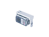
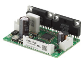
Actuator/Control Circuit
This product is currently no longer available for sale
| Product Classification | Product Name | List Price | List Price | Shipping Date |
|---|---|---|---|---|
| Actuator / Control Circuit | DRL28PA1G-03G | SGD 1,288 | USD 1,030 | Discontinued Product (31.3.2019 discontinued) |
Included
- Actuator, Control Circuit, Connector Housing, Contact, Operating Manual
Specifications
Other Specifications
Others Reference Diagrams for Load Moment
Load Moment
Maximum Transportable Mass
Repetitive Positioning Accuracy
Electromagnetic Brake Specifications
| Electromagnetic Brake Type | Power off activated type |
|---|---|
| Power Supply Input Voltage/Current |
DRL42: 24 VDC±5 % 0.08 A DRL60: 24 VDC±5 % 0.25 A |
| Brake Activation/Release Time | Activation time: 20 ms Release time: 30 ms |
| Time Rating | Continuous |
Driver Circuit Specifications
| Driver Product Name | CRD5103P | CRD5107P | CRD5114P | |
|---|---|---|---|---|
| Power Supply Input | Voltage | 24 VDC±10 % | ||
| Current | 0.7 A | 1.4 A | 2.5 A | |
| Input Signals | Input Mode | Photocoupler input, input resistance 220 Ω, input current 7~20 mA, photocoupler "ON": +4.5~5.25 V, photocoupler "OFF": 0~1 V (voltage between terminals) |
||
| CW Pulse Signal (Pulse Signal) |
CW (forward) direction operation command pulse signal (operation command pulse signal when in 1-pulse input mode), negative logic pulse input Pulse width 1 μs min., rise/fall time 2 μs max., pulse duty 50 % max. When pulse input is turned from "ON" to "OFF," the screw shaft moves 1 step in the forward direction. Maximum input pulse frequency 500 kHz (at 50 % pulse duty) |
|||
| CCW Pulse Signal (Travel Direction Signal) |
CCW (backward) direction operation command pulse signal (when in 1-pulse input mode, travel direction signal photocoupler "ON": CW, Photocoupler "OFF": CCW), negative logic pulse input Pulse width 1 μs min., rise/fall time 2 μs max., pulse duty 50 % max. When pulse input is turned from "ON" to "OFF," the screw shaft moves 1 step in the backward direction. Maximum input pulse frequency 500 kHz (at 50 % pulse duty) |
|||
| Resolution Select Signal | DATA1 when the photocoupler is "OFF," DATA2 when the photocoupler is "ON." | |||
| All Windings Off Signal | When the photocoupler is "ON," the output current to the actuator is turned OFF. When the photocoupler is "OFF," the output current to the actuator is turned ON. |
|||
| Current Cutback Release Signal | When the photocoupler is "ON," the automatic current cutback function for when the actuator stops is canceled. When the photocoupler is "OFF," the automatic current cutback function is activated when the actuator stops (after approx. 100 ms). |
|||
| Output Signals | Output Mode | Photocoupler and open-collector output external use conditions: 24 VDC 10 mA max. | ||
| Excitation Timing Signal | This signal is output when the excitation sequence is step "0." (Photocoupler: ON) When 1 Step: Output once every 10 pulses When 10 Steps: Output once every 100 pulses |
|||
| Functions | Automatic current cutback, resolution select switching, pulse input mode switching, smooth drive function, all windings off, excitation timing | |||
| Cooling Method | Natural cooling method | |||
General Specifications
Values are after rated operation at normal ambient temperature and humidity.
| Specifications | Actuator Section | Driver | |
|---|---|---|---|
| Motor Thermal Class | 130 (B) [UL/CSA Standard obtainment is certified with 105(A)] |
− | |
| Insulation Resistance | 100 MΩ or more when a 500 VDC megger is applied between the motor windings and the case. | − | |
| Dielectric Strength |
No abnormality is observed when the following is applied between the motor windings and the case of the motor for 1 minute.
|
− | |
| Operating Environment (When Operating) |
Ambient Temperature | 0~+40 °C (Non-freezing) | |
| Ambient Humidity | 85 % max. (Non-condensing) | ||
| Atmosphere | No corrosive gases or dust. No exposure to water, oil or other liquids. | ||
Note
- Do not measure insulation resistance or perform a dielectric strength test while the actuator and driver are connected.
System Configuration
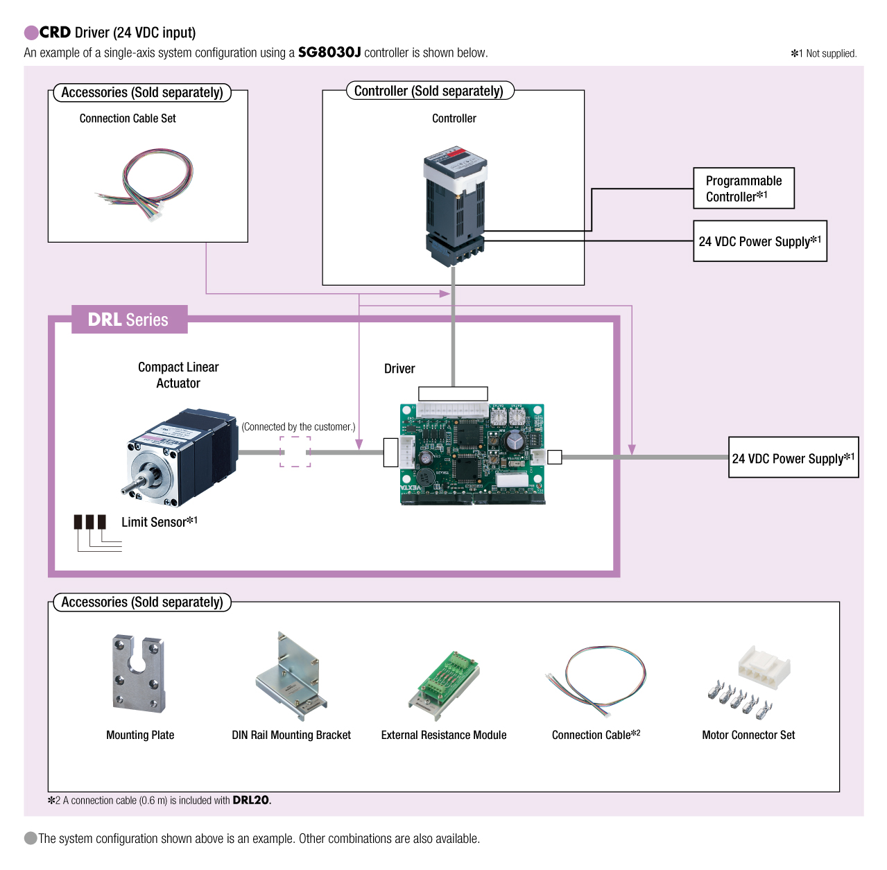
Cables and Accessories
close