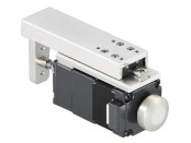
Compact Electric Cylinders DRLII Series Built-In Controller Type
DRL28G-03B1PN-KD

Actuator/Control Circuit
| Product Classification | Product Name | List Price | List Price | Shipping Date |
|---|---|---|---|---|
| Actuator / Control Circuit | DRL28G-03B1PN-KD | SGD 1,570 | USD 1,256 | Product to be Discontinued (30.1.2026 order deadline) |
- *Please contact us regarding purchasing of product.
- *Product will be discontinued on 31.3.2026. Please place your order before the order deadline.
Included
- Actuator, Control Circuit, Power Supply Connector (CN1), Connection Cable (For I/O Signal, CN2), Connection Cable (For Actuator Connection, CN4), Connection Cable (For Connector Connection of Actuator), Operating Manual
Specifications
Dimensions
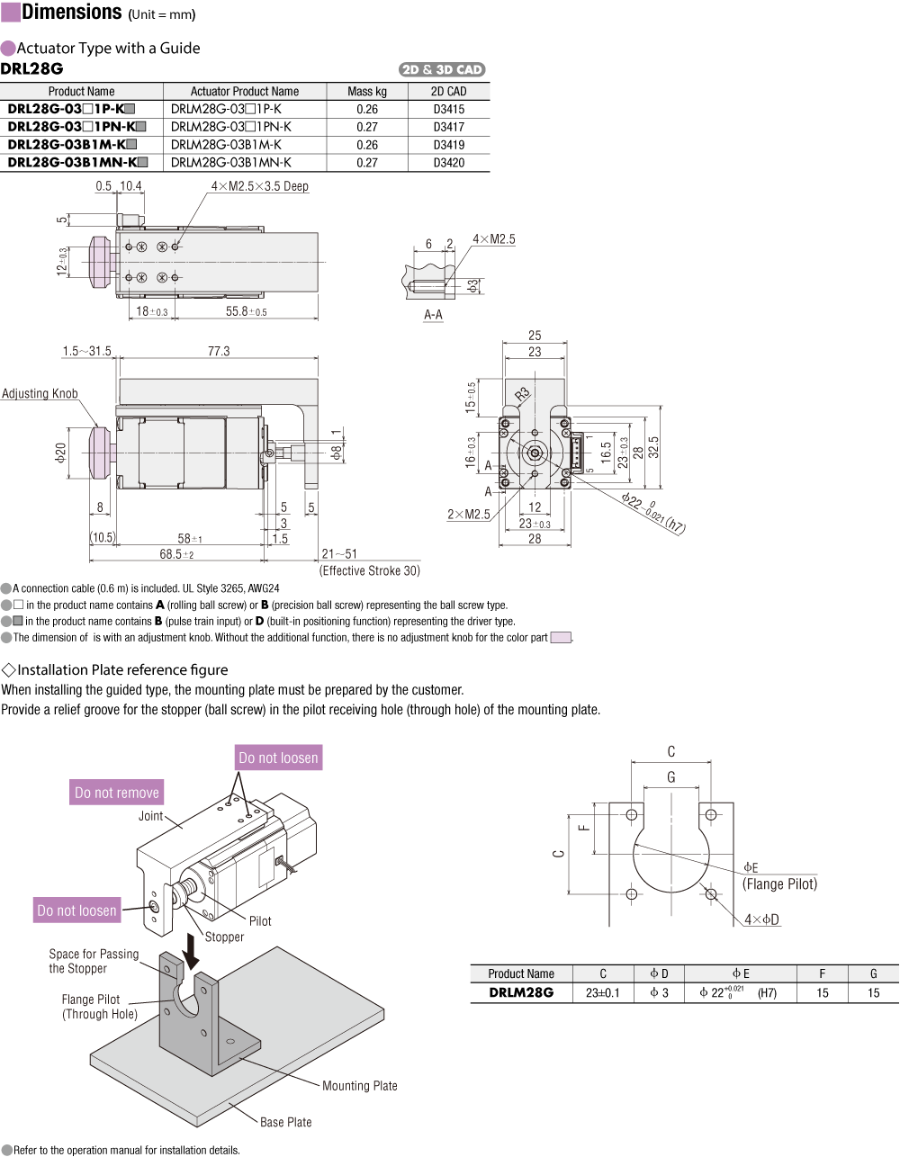
Actuator
Data Download
Other Specifications
General Specifications
| Specifications | Actuator Section | Driver | ||
|---|---|---|---|---|
| Built-in Controller | Pulse Input | |||
| Thermal Class | 130(B) [UL/CSA Standard obtainment is certified with 105(A)] |
- | - | |
| Insulation Resistance | 100 MΩ or more when a 500 VDC megger is applied between the motor windings and the case. |
100 MΩ or more when a 500 VDC megger is applied between the following places:
|
||
| Dielectric Strength |
No abnormality is observed when the following is applied between the motor windings and the case of the motor for 1 minute.
|
- | - | |
| Operating Environment (When operating) |
Ambient Temperature | 0~40 °C* (non-freezing) *DRL20V, DRL28V can range from 5~40 °C. | ||
| Ambient Humidity | 85 % max. (Non-condensing) | |||
| Atmosphere | No corrosive gases or dust. No exposure to water, oil or other liquids. | |||
| Degree of Protection | IP00 | IP10 | IP20 | |
Driver Circuit Specifications
| Driver Type | Built-in Controller | Pulse Input | ||
|---|---|---|---|---|
| Driver Product Name | LRD503-KD, LRD507-KD, LRD514-KD | LRD503-K, LRD507-K, LRD514-K | ||
| Power Supply Input | 24 VDC±10 % | LRD503-KD: 0.7 A LRD507-KD: 1.4 A LRD514-KD: 2.5 A |
24 VDC±10 % | LRD503-K: 0.7 A LRD507-K: 1.4 A LRD514-K: 2.5 A |
| Maximum Input Pulse Frequency | - | Line Driver Output by Host Controller: 500 kHz (When the pulse duty is 50 %) Open-Collector Output by Host Controller: 250 kHz (When the pulse duty is 50 %) |
||
| Input Signals | Input Mode: Photocoupler input | Input Mode: Photocoupler input | ||
| CW Pulse Signal (Pulse signal) CW (forward) direction operation command pulse signal (Operation command pulse signal when 1-pulse input mode is used) Negative logic pulse input, pulse width 1 μs or more, rise and fall time 2 μs or less, pulse duty 50 % or less When pulse input is turned from "ON" to "OFF," the screw shaft moves 1 step in the forward direction. |
||||
| CCW pulse signal (travel direction signal) CCW (backward) direction operation command pulse signal (when in 1-pulse input mode, travel direction signal photocoupler "ON": CW, Photocoupler "OFF": CCW) Negative logic pulse input, pulse width 1 μs or more, rise and fall time 2 μs or less, pulse duty 50 % or less When pulse input is turned from "ON" to "OFF," the screw shaft moves 1 step in the backward direction. |
||||
| All Windings Off Signal When the photocoupler is "ON," the output current to the actuator is turned OFF. When the photocoupler is "OFF," the output current to the actuator is turned ON. |
||||
| Step Angle Select Input Signal Selects the step angle setting switch when the photocoupler is "OFF" and the basic step angle when the photocoupler is "ON." |
||||
| Automatic Current Cutback Release Signal When the photocoupler is "ON," the automatic current cutback function for when the actuator stops is canceled. When the photocoupler is "OFF," the automatic current cutback function is activated when the actuator stops (after approx. 100 ms). |
||||
| Output Signals | Output Format: Photocoupler and Open-Collector Output Line Driver Output PLS-OUT, DIR-OUT |
Output Format: Photocoupler and open-collector output | ||
| Excitation Timing Signal This signal is output when the excitation sequence is step "0." (Photocoupler: ON) For a Resolution of 1: output once every 10 pulses For a Resolution of 10: output once every 100 pulses |
||||
| Number of Positioning Data Sets | 63 points | - | ||
| Positioning Operation | Single, linked, linked 2, sequential | - | ||
| Other operations | JOG operation, return-to-home operation, continuous operation, test operation | - | ||
| Control Module OPX-2A | ○ | - | ||
| Support Software MEXE02 | ○ | - | ||
| Function | Smooth drive, automatic current cutback, step angle switching, pulse input mode switching (pulse input only), all windings off, excitation timing | |||
| Cooling Method | Natural Cooling Method | |||
RS-485 Communication Specifications
| Protocol | Modbus Protocol (Modbus RTU mode) |
|---|---|
| Electrical Characteristics | EIA-485 Compliant, straight cable Use twisted-pair cables (TIA/EIA-568B CAT5e or better recommended). The max. total extension length is 50 m.* |
| Mode | Half duplex communication and asynchronous mode (data: 8 bits, stop bit: 1 bit or 2 bits, parity: none, even, or odd) |
| Transmission Rate | 9600 bps/19200 bps/38400 bps/57600 bps/115200 bps |
| Connection Type | Up to 31 units can be connected to a single programmable controller (master device). |
- *If a specific wiring and layout causes the actuator cable or power supply cable to generate a noise problem, shield the cable or use ferrite cores.
Standards
Regulations and Standards Materials
Documents about compliance with regulations and standards can be downloaded from the "Data Download" tab on the product details page.
(The types of files available for download vary by product.)
Explanations of the Global Laws, Regulations and Standards can be found here.
Information about our compliance with regulations and standards for each of our product series can be found here.
Hazardous Substances
The product does not contain any substances (10 substances) exceeding the regulation values of the RoHS Directive (2011/65/EU, 2015/863/EU).
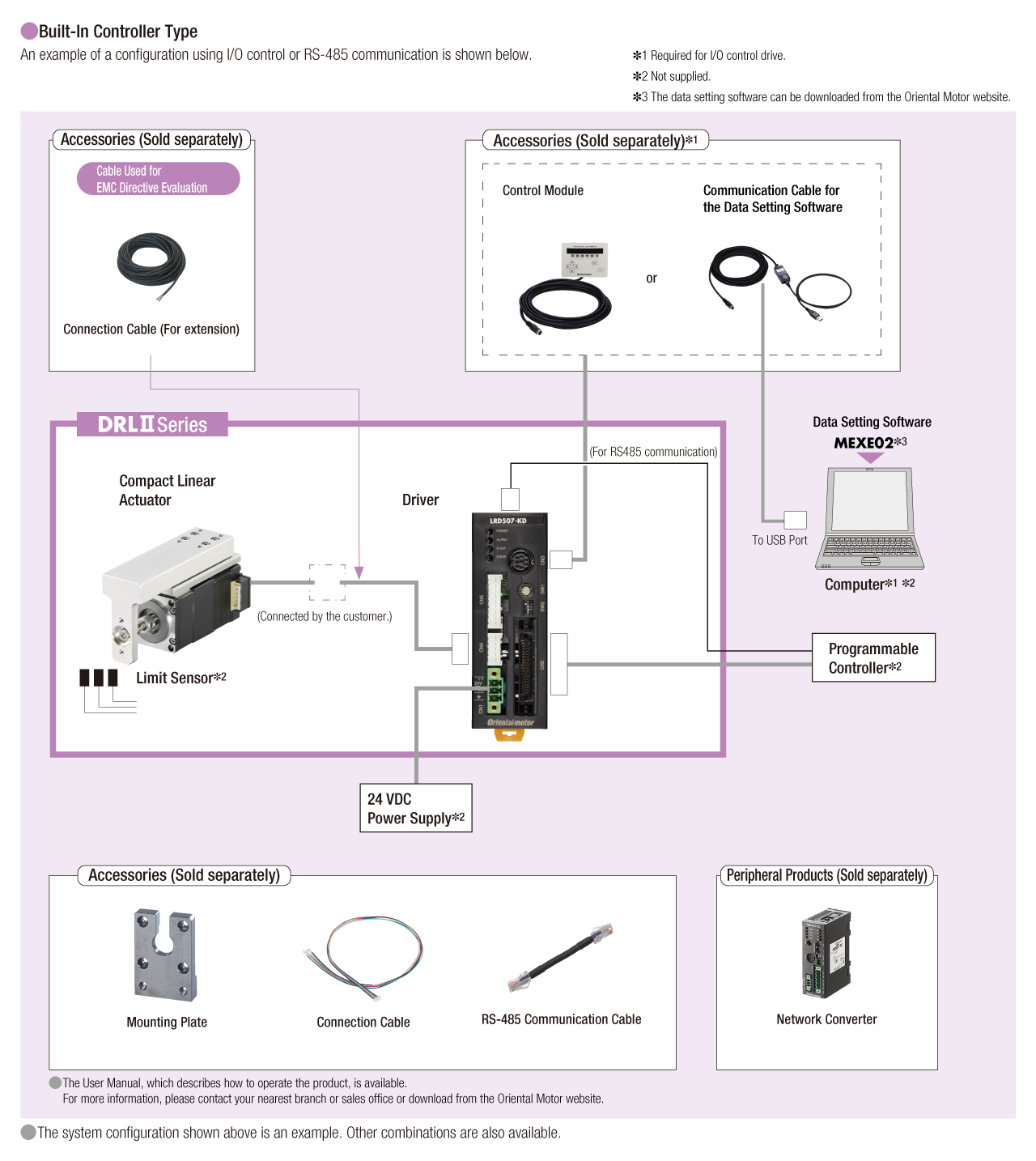
System Configuration
Related Products
| Products | Features | ||
|---|---|---|---|
NETC02-CC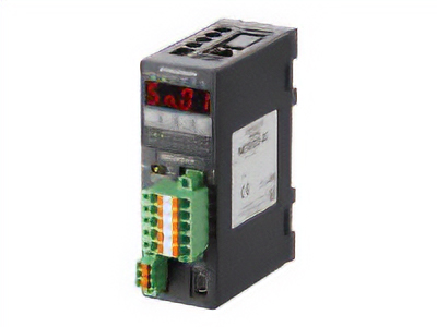
|
Features |
[CC-Link Ver. 2 Compatible] By supporting CC-Link Ver.2, you can simplify the ladder program and shorten the communication time for data sending and receiving. |
|
| Products |
NETC01-CC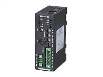
|
Features |
[CC-Link Ver.1.1 Compatible] By connecting a network converter, you can complete the wiring process with a single dedicated cable approved for the CC-Link communication protocol. |
| Products |
NETC01-M2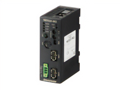
|
Features |
[MECHATROLINK-II Compatible] By connecting a network converter, the wiring process can be completed with a single dedicated cable approved for the MECHATROLINK-II communication protocol. |
| Products |
NETC01-M3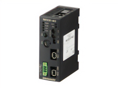
|
Features |
[MECHATROLINK-III Compatible] By connecting a network converter, the wiring process can be completed with a single dedicated cable approved for the MECHATROLINK-III communication protocol. |
| Products |
NETC01-ECT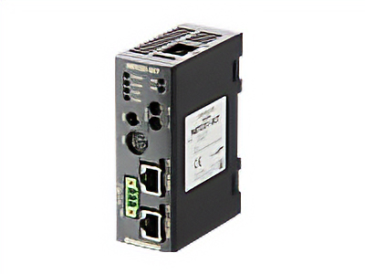
|
Features |
[EtherCAT Compatible] |