Brushless Motors BXII Series
BXS460C-30FR-3
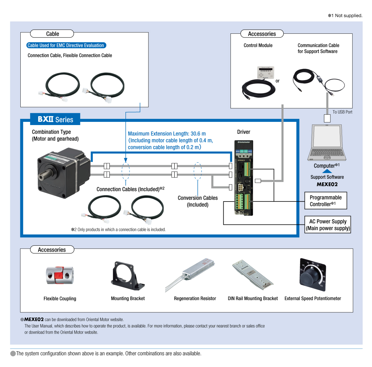
Gearhead / Motor / Control Circuit
| Product Classification | Product Name | List Price | List Price | Shipping Date |
|---|---|---|---|---|
| Gearhead / Motor / Control Circuit | BXS460C-30FR-3 | SGD 1,095 | USD 876 | Discontinued Product (31.3.2022 discontinued) |
Included
- Motor, Gearhead, Control Circuit, Conversion Cable, Connection Cable, Connector for CN1, Connector for CN5, Connector for CN7, Mounting Bracket for Control Circuit (with Screws), Mounting Screws, Parallel Key, Safety Cover (with Screws)
Specifications
Characteristics
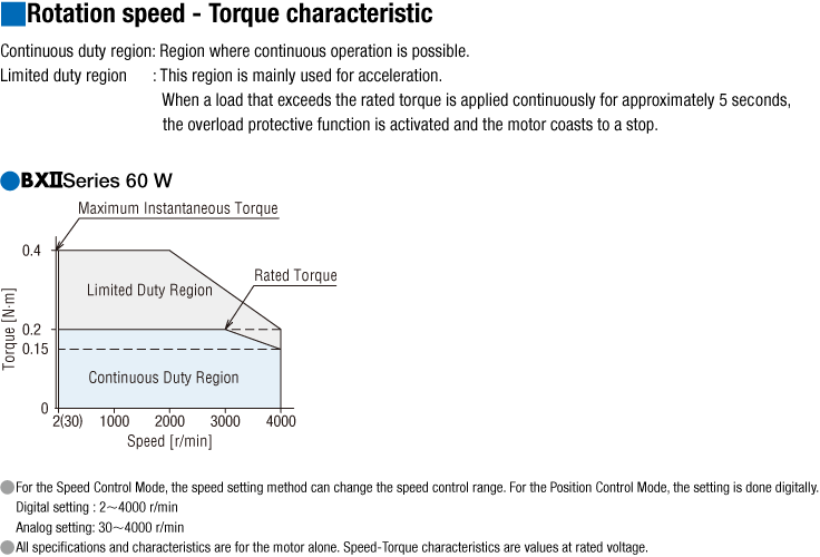
Speed - Torque Characteristics
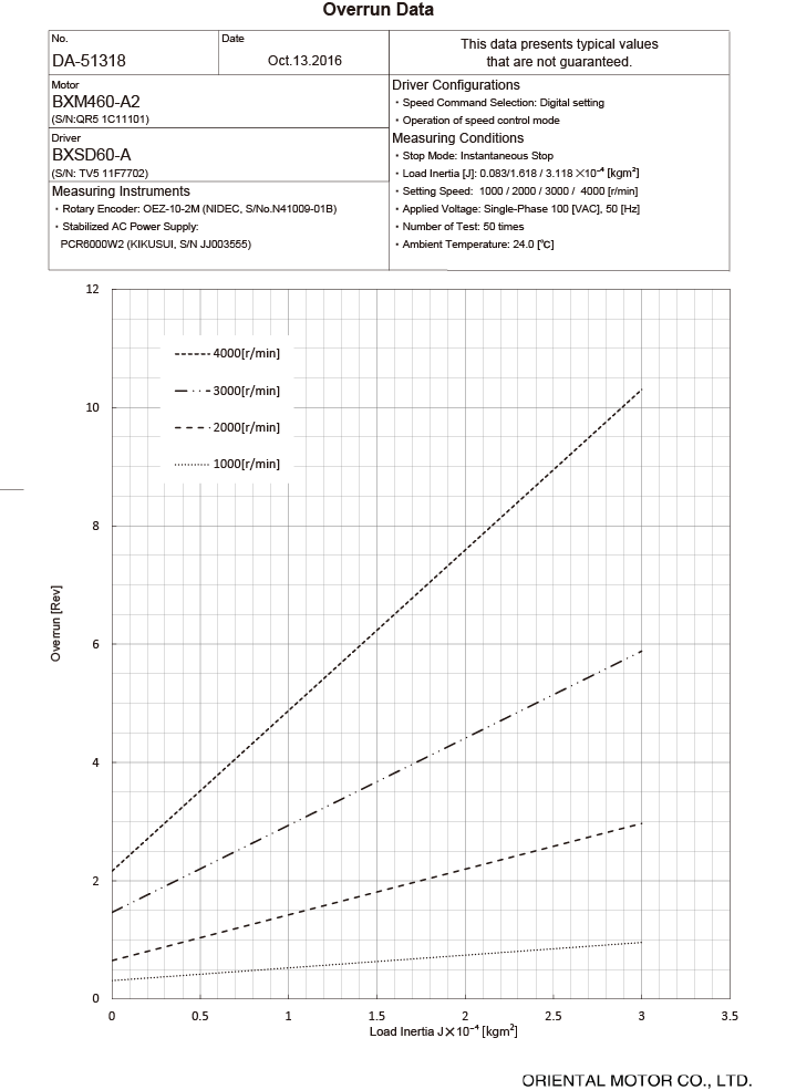
Overrun (Representative Value)
Data Download
Other Specifications
Common Specifications
| Item | Speed Control Mode | Position Control Mode |
|---|---|---|
| Input Signals | Photocoupler Input Input Resistance: 6.6 kΩ Operated by Internal Power Supply: 5 VDC Connectable External Power Supply: 24 VDC −15∼+20% 100 mA min. Sink input/source input Supported through external wiring |
|
| Arbitrary signal assignment to IN0∼IN8 input (9 points) is possible. []: Initial setting [FWD], [RVS], [M0], [M1], [M2], [M3], [FREE], [STOP], [ALM-RST], TH, TL, S-ON, HMI, [Not Used] |
Arbitrary signal assignment to IN0∼IN8 input (9 points) is possible. [ ]: Initial setting [START], [M0], [M1], [M2], [M3], [FREE], [STOP], [ALM-RST], [HOME], [HOMES], TH, SSTART, MS0, MS1, MS2, MS3, MS4, MS5, FWD, RVS, +JOG, -JOG, S-ON, P-PRESET, TL, HMI, Not Used |
|
| Output Signals | Photocoupler and Open-Collector Output External Power Supply: 4.5~30 V DC, 100 mA max. Sink Output/Source Output Supported through external wiring |
|
| Arbitrary signal assignment to OUT0∼OUT2 output (3 points) is possible. [ ]: Initial setting [ALM], [WNG], [MOVE], END, TLC, VA, ZSG |
Arbitrary signal assignment to OUT0∼OUT2 output (3 points) is possible. [ ]: Initial setting [ALM], WNG, MOVE, [READY], [HOME-P], END, TLC, VA, ZSG |
|
| Transistor and Open-Collector Output External Power Supply: 4.5~30 V DC, 20 m max. |
||
| ASG, BSG 500 pulses/revolution | ||
| Protective Functions | When the following protective functions are activated, the ALM output turns OFF and the motor will stop. The alarm code will be displayed on the operation panel at the same time. Excessive Position Deviation*, The following errors occur: overcurrent, overvoltage, undervoltage, sensor error, main circuit output error, overload, overspeed, and EEPROM error, initial sensor error, prevention of operation at power-on, regeneration resistor overheat, software overtravel*, operation data* |
|
| Maximum Extension Distance | Motor and Driver Distance: 30.7 m (when a connection cable (sold separately) is used) | |
| Time Rating | Continuous | |
- *For position control mode only
General Specifications
| Item | Motor | Driver | |
|---|---|---|---|
| Insulation Resistance | 100 MΩ or more when a 500 VDC megger is applied between the windings and the case after continuous operation under normal ambient temperature and humidity. (Except for the encoder) |
After continuous operation at normal ambient temperature and humidity, the measurement value between the power supply terminal and the protective earth terminal or the power supply terminal and the signal I/O terminal is 100 MΩ min. using a 500 VDC megger. |
|
| Dielectric Strength | No abnormality is observed even with an application of 1.5 kVAC at 50 Hz between the coils and the case for 1 minute after continuous operation at normal ambient temperature and humidity. (Except for the encoder) |
After continuous operation at normal ambient temperature and humidity, no abnormality is observed even if 50 Hz, 1.5 kVAC is applied between the power supply terminal and the protective earth terminal, and 50 Hz, 1.5 kVAC is applied between the power supply terminal and the I/O signal terminal for 1 minute. |
|
| Temperature Rise | After continuous operation at normal ambient temperature and humidity, the temperature rise of the windings measured by the thermocouple method is less than 50° C, and the measured temperature rise on the case surface is less than 40 °C*1. |
After continuous operation at normal ambient temperature and humidity, the measurement value of the temperature rise of the heat sink is 50 °C max. using the thermocouple method. (60 °C max. when 200 W and 400 W types are installed in contact with each other) |
|
| Operating Environment*2 | Ambient Temperature | 0~+50 °C (Non-freezing) | 0~+50 °C (Non-freezing)*2
0~+40 °C for 200 W and 400 W types when mounted close together |
| Ambient Humidity | 85 % max. (Non-condensing) | ||
| Altitude | Less than 1000 m above sea level | ||
| Atmosphere | No corrosive gases or dust Cannot be used in a radioactive area, magnetic field, vacuum, or other special environments. |
||
| Vibration | Not subject to continuous vibration or excessive shock In conformance with JIS C 60068-2-6, "Sine-wave vibration test method" Frequency Range: 10~55 Hz, Single Amplitude: 0.15 mm, Sweep Directions: 3 directions (X, Y, Z), Number of Sweeps: 20 |
||
| Storage Conditions*3 | Ambient Temperature | -20~+60°C (Non-freezing) | -25~+70°C (Non-freezing) |
| Ambient Humidity | 85 % max. (Non-condensing) | ||
| Altitude | Less than 3000 m above sea level | ||
| Atmosphere | No corrosive gases or dust Should not be exposed to water or oil. Cannot be used in a radioactive area, magnetic field, vacuum, or other special environments. | ||
| Thermal Class | UL/CSA Standards: 105 (A), EN Standards: 120 (E) | − | |
| Degree of Protection | IP54 (Excluding the installation surface of the round shaft type and connectors) | IP20 | |
- *1
- Attach round shaft types to a heat sink (Material: aluminum) of one of the following sizes to maintain a motor case surface temperature of 90 °C max.
30 W Type: 115×115 mm, 5 mm thickness, 60 W Type: 135×135 mm, 5 mm thickness, 120 W Type: 165×165 mm, 5 mm thickness,
200 W Type: 200 × 200 mm, 5 mm thickness 400 W Type: 250 × 250 mm, 6 mm thickness - Characteristics *2
- Install the driver to a location that has the same heat radiation capability as an aluminum metal plate.
Single mounting: 200 x 200 mm, 2 mm thick
Close Mounting 350x350 mm, 2 mm thickness
For 200 W and 400 W types: Load factor is 90% or less when using driver mounting brackets or DIN rail mounting brackets (sold separately). - *3
- The value for storage condition applies to short periods such as the period during transport.
- Do not measure insulation resistance or perform a dielectric strength test the motor and driver are connected.
Speed Control Mode Specifications
| Item | Digital setting | Analog Setting |
|---|---|---|
| Speed Control Range | 2~4000 r/min (Set in 1 r/min increments) | 30~4000 r/min |
| Speed Setting Method |
Set using one of the following methods.
|
Set using one of the following methods. Operation Data No. 0:
Internal Speed Potentiometer (SPEED)
Operation Data No. 1:
|
| Acceleration/Deceleration Time | 0.000~30.00s (Rated speed, no load) |
0.1~30s (Rated speed, no load) |
| Acceleration/Deceleration Time Setting Method |
Set using one of the following methods. (Individual settings)
|
Acceleration time/deceleration time are common to Operation Data No. 0 and No. 1
|
| Torque Limiting Setting Range | 0~250% | |
| Torque Limiting Setting Methods |
Set using one of the following methods.
|
Set using one of the following methods.
|
| Operation Data Setting Number | 16 Points | |
| Operation During Motor Standstill | Operations can be selected when the motor is at standstill. ・Motor non-excitation (initial setting) / ・Servo lock stop (motor excitation) |
|
| Other Operations | JOG operation, test operation, teaching (Excluding MEXE02 *1) | |
- *1
- The support software MEXE02 can be downloaded from the website. When using MEXE02, the communication cable for support software CC05IF-USB (sold separately) is needed.
- *2
- The maximum voltage can be arbitrarily changed with the parameters. Example: 0~5 VDC
Position Control Mode Specifications
| Item | Digital Setting | |
|---|---|---|
| Positioning Operation |
Traveling Amount Setting Range | −8,388,608~+8,388,607step |
| Resolution | 0.72˚ (500 steps/revolution) | |
| Speed Setting Range | 2~4000 r/min (Set in 1 r/min increments) | |
| Operating Mode | Incremental or Absolute | |
| Operation Functions | Independent, Linked, Linked 2, Sequential, Direct | |
| Acceleration/Deceleration Time | 0.000~30.00s (Rated speed, no load) |
|
| Torque Limiting | 0~250% | |
| Operation Data Setting Number | 31 Points | |
| How to Set Operating Data | Set using one of the following methods.· ・Operation Panel・MEXE02 * ・OPX-2A(sold separately) (Torque limiting alone can be done with external analog settings as well) |
|
| Other Operations | Continuous operation, JOG operation, return-to-home operation, test operation, teaching | |
- *The support software MEXE02 can be downloaded from the website. When using MEXE02, the communication cable for support software CC05IF-USB (sold separately) is needed.
Torque Limiting Function
The motor's output torque can be limited in speed control mode and position control mode.
| Item | Specifications |
|---|---|
| Torque Limiting Setting Command |
Set 1 method from the following.
The same torque limiting value applies to all operation data. |
| Torque Limiting Setting Range*2 |
Assuming that the rated torque of the motor is 100%, torque limiting value can be set in the following ranges.
|
- *1
- The maximum voltage can be arbitrarily changed with the parameters. Example: 0~5 VDC
- *2
- Do not add a load that exceeds the maximum instantaneous torque.
Note
- An error up to a max. of approximately ±10 % (at rated torque and rated speed) may occur between the setting value and generated torque due to the setting speed, power supply voltage and motor cable extension length.
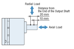
Permissible Radial Load and Permissible Axial Load
Parallel Shaft Gearhead
| Motor Product Name | Gear Ratio | Permissible Radial Load | Permissible Axial Load N |
||
|---|---|---|---|---|---|
| 10 mm From the End of the Output Shaft N |
20 mm From the End of the Output Shaft N |
||||
| BXM230 | 5 | At 2~3000 r/min | 100 | 150 | 40 |
| At 4000 r/min | 90 | 110 | |||
| 10, 15, 20 | At 2~3000 r/min | 150 | 200 | ||
| At 4000 r/min | 130 | 170 | |||
| 30, 50, 100, 200 | At 2~3000 r/min | 200 | 300 | ||
| At 4000 r/min | 180 | 230 | |||
| BXM460 | 5 | At 2~3000 r/min | 200 | 250 | 100 |
| At 4000 r/min | 180 | 220 | |||
| 10, 15, 20 | At 2~3000 r/min | 300 | 350 | ||
| At 4000 r/min | 270 | 330 | |||
| 30, 50, 100, 200 | At 2~3000 r/min | 450 | 550 | ||
| At 4000 r/min | 420 | 500 | |||
| BXM5120 | 5 | At 2~3000 r/min | 300 | 400 | 150 |
| At 4000 r/min | 230 | 300 | |||
| 10, 15, 20 | At 2~3000 r/min | 400 | 500 | ||
| At 4000 r/min | 370 | 430 | |||
| 30, 50, 100, 200 | At 2~3000 r/min | 500 | 650 | ||
| At 4000 r/min | 450 | 550 | |||
| BXM6200 BXM6400 |
5, 10, 15, 20 | At 2~3000 r/min | 550 | 800 | 200 |
| At 4000 r/min | 500 | 700 | |||
| 30, 50 | At 2~3000 r/min | 1000 | 1250 | 300 | |
| At 4000 r/min | 900 | 1100 | |||
| 100, 200 | At 2~3000 r/min | 1400 | 1700 | 400 | |
| At 4000 r/min | 1200 | 1400 | |||
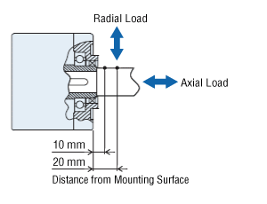
About Load Position
Hollow Shaft Flat Gearhead
| Motor Product Name | Gear Ratio | Permissible Radial Load | Permissible Axial Load N |
||
|---|---|---|---|---|---|
| 10 mm from the Gearhead Mounting Surface N |
20 mm from the Gearhead Mounting Surface N |
||||
| BXM230 | 5, 10 | At 2~3000 r/min | 450 | 370 | 200 |
| At 4000 r/min | 410 | 330 | |||
| 15, 20, 30, 50, 100, 200 | At 2~3000 r/min | 500 | 400 | ||
| At 4000 r/min | 460 | 370 | |||
| BXM460 | 5, 10 | At 2~3000 r/min | 800 | 660 | 400 |
| At 4000 r/min | 730 | 600 | |||
| 15, 20, 30, 50, 100, 200 | At 2~3000 r/min | 1200 | 1000 | ||
| At 4000 r/min | 1100 | 910 | |||
| BXM5120 | 5, 10 | At 2~3000 r/min | 900 | 770 | 500 |
| At 4000 r/min | 820 | 700 | |||
| 15, 20 | At 2~3000 r/min | 1300 | 1110 | ||
| At 4000 r/min | 1200 | 1020 | |||
| 30, 50, 100, 200 | At 2~3000 r/min | 1500 | 1280 | ||
| At 4000 r/min | 1400 | 1200 | |||
| BXM6200 BXM6400 |
5*, 10 | At 2~3000 r/min | 1230 | 1070 | 800 |
| At 4000 r/min | 1130 | 990 | |||
| 15, 20 | At 2~3000 r/min | 1680 | 1470 | ||
| At 4000 r/min | 1550 | 1360 | |||
| 30, 50, 100 | At 2~3000 r/min | 2040 | 1780 | ||
| At 4000 r/min | 1900 | 1660 | |||
- * 400 W type only
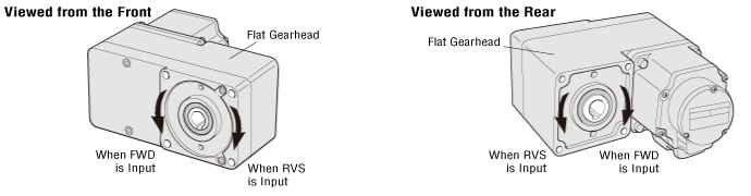
Rotation Direction
Round Shaft Type
| Motor Product Name | Permissible Radial Load | Permissible Axial Load N |
|
|---|---|---|---|
| 10 mm From the End of the Output Shaft N |
20 mm From the End of the Output Shaft N |
||
| BXM230 | 87.2 | 107 | 10 |
| BXM460 | 117 | 137 | 20 |
| BXM5120 | 156 | 176 | 25 |
| BXM6200 BXM6400 |
197 | 221 | 25 |
Permissible Radial Load Calculation
Permissible Radial Load Calculation
The formula for calculating the permissible radial load varies depending on the mechanism.
When One Side of the Load Shaft is Not Supported by the Bearing Unit
The radial load is the most difficult mechanism. A Stepped Type Load Shaft is recommended.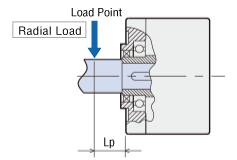
| Product Name | Permissible Radial Load W [N] |
|---|---|
| GFS2G□FR |
\(\begin{align} \mathrm{W} [\mathrm{N}] = \frac{36}{36 + \mathrm{Lp}} \times \mathrm{F}_0 [\mathrm{N}] \end{align}\)
|
| GFS4G□FR |
\(\begin{align} \mathrm{W} [\mathrm{N}] = \frac{40}{40 + \mathrm{Lp}} \times \mathrm{F}_0 [\mathrm{N}] \end{align}\)
|
| GFS5G□FR |
\(\begin{align} \mathrm{W} [\mathrm{N}] = \frac{50}{50 + \mathrm{Lp}} \times \mathrm{F}_0 [\mathrm{N}] \end{align}\)
|
| GFS6G□FR |
\(\begin{align} \mathrm{W} [\mathrm{N}] = \frac{60}{60 + \mathrm{Lp}} \times \mathrm{F}_0 [\mathrm{N}] \end{align}\)
|
When One Side of the Load Shaft is Supported by the Bearing Unit
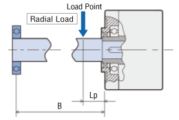
| Product Name | Permissible Radial Load W [N] |
|---|---|
| GFS2G□FR GFS4G□FR GFS5G□FR GFS6G□FR |
\(\begin{align} \mathrm{W} [\mathrm{N}] = \frac{\mathrm{B}}{\mathrm{B} - \mathrm{Lp}} \times \mathrm{F}_0 [\mathrm{N}] \end{align}\)
|
| Product Name | Speed | Gear Ratio | F0 [N] |
|---|---|---|---|
| GFS2G□FR | At 2~3000 r/min | 5, 10 | 570 |
| 15~200 | 630 | ||
| At 4000 r/min | 5, 10 | 520 | |
| 15~200 | 580 | ||
| GFS4G□FR | At 2~3000 r/min | 5, 10 | 1000 |
| 15~200 | 1500 | ||
| At 4000 r/min | 5, 10 | 910 | |
| 15~200 | 1370 | ||
| GFS5G□FR | At 2~3000 r/min | 5, 10 | 1080 |
| 15, 20 | 1550 | ||
| 30~200 | 1800 | ||
| At 4000 r/min | 5, 10 | 980 | |
| 15, 20 | 1430 | ||
| 30~200 | 1680 | ||
| GFS6G□FR | At 2~3000 r/min | 5, 10 | 1430 |
| 15, 20 | 1960 | ||
| 30~100 | 2380 | ||
| At 4000 r/min | 5, 10 | 1320 | |
| 15, 20 | 1810 | ||
| 30~100 | 2210 |
System Configuration