Brushless Motors BMU Series
BLM460SP-152
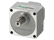
Motor
This product is currently no longer available for sale
| Product Classification | Product Name | List Price | List Price | Shipping Date |
|---|---|---|---|---|
| Motor | BLM460SP-152 | SGD 270 | USD 216 | Discontinued Product (31.3.2019 discontinued) |
Included
- Motor: None
Gearhead: Mounting Screws, Parallel Key
Specifications
Data Download
Other Specifications
General Specifications
| Item | Motor | Driver | |
|---|---|---|---|
| Insulation Resistance | 100 MΩ or more when a 500 VDC megger is applied between the windings and the case after continuous operation under normal ambient temperature and humidity. |
After continuous operation at normal ambient temperature and humidity, the value measured with a 500 VDC megger between the power supply terminal and the protective earth terminal, and between the power supply terminal and the I/O signal terminal is 100 MΩ min. |
|
| Dielectric Strength | No abnormality is observed when 1.5 kVAC at 50 Hz applied between the coils and case for 1 minute after continuous operation under normal ambient temperature and humidity. |
After continuous operation at normal ambient temperature and humidity, no abnormality is observed even if 50 Hz, 1.5 kVAC is applied between the power supply terminal and the protective earth terminal, and 50 Hz, 1.5 kVAC is applied between the power supply terminal and the I/O signal terminal for 1 minute. |
|
| Temperature Rise | After rated continuous operation at normal ambient temperature and humidity, the temperature rise of the coil measured value by the thermocouple method is max. 50 °C (max. 60 °C for 400 W), and the measured value of the temperature rise of the case surface is max. 40 °C (max. 50 °C for 400 W) *1. |
After continuous operation at normal ambient temperature and humidity, the measurement value of the temperature rise of the heat sink is 50 °C max. using the thermocouple method. |
|
| Operating Environment | Ambient Temperature | 0~+40°C (Non-freezing) | 0~+40°C (Non-freezing) 0~+40°C (Non-freezing) [0~+35 °C (non-freezing) only when the front side of the 400 W type driver is installed facing upward. The front side of the driver is the side with the display and setting dials.] |
| Ambient Humidity | 85 % max. (Non-condensing) | ||
| Altitude | Up to 1000 m above sea level | ||
| Atmosphere | No corrosive gases or dust Cannot be used in a radioactive area, magnetic field, vacuum, or other special environments. | ||
| Vibration | Not subject to continuous vibration or excessive shock In conformance with JIS C 60068-2-6, "Sine-wave vibration test method" Frequency Range: 10~55 Hz, Half Amplitude: 0.15 mm, Sweep Direction: 3 directions (X, Y, Z), Number of Sweeps: 20 times |
||
| Storage Conditions*2 | Ambient Temperature | -20~+70°C (Non-freezing) | -20~+70°C (Non-freezing) |
| Ambient Humidity | 85 % max. (Non-condensing) | ||
| Altitude | Up to 3000 m above sea level | ||
| Thermal Class | Standard Type (IP40 rating), IP65 Rating: UL/CSA Standards 105 (A), EN Standards 120 (E) | − | |
| Degree of Protection *3 |
Standard Type (IP40 rating):
IP40
IP65 Rating:
IP65 (Excluding the installation surface of the round shaft type and connectors)
|
IP20 | |
- *1
- Attach round shaft types to a heat sink (Material: aluminum) of one of the following sizes to maintain a motor case surface temperature of 90 °C max.
30 W Type: 115×115 mm, 5 mm thickness, 60 W Type: 135×135 mm, 5 mm thickness, 120 W Type: 165×165 mm, 5 mm thickness,
200 W Type: 200×200 mm, 5 mm thickness, 400 W Type: 250×250 mm, 6 mm thickness - *2
- The value for storage condition applies to short periods such as the period during transport.
- *3
- The IP indication that shows the watertight and dust-resistant performance are specified under IEC 60529 and IEC 60034-5.
Note
- Do not measure insulation resistance or perform a dielectric strength test the motor and driver are connected.
Motor Material and Surface Treatment
Materials
Case: Aluminum
Output Shaft: Standard Type (IP40 rating), IP65 Rating: S45C
Screw: Stainless Steel (externally exposed parts only. protective earth terminal excluded)
Output Shaft: Standard Type (IP40 rating), IP65 Rating: S45C
Screw: Stainless Steel (externally exposed parts only. protective earth terminal excluded)
Surface Treatment
Case: Painted (except for mounting surface)
Permissible Radial Load and Permissible Axial Load
Parallel Shaft Gearhead
| Output | Gear Ratio | Permissible Radial Load | Permissible Axial Load N |
||
|---|---|---|---|---|---|
| 10 mm From the End of the Output Shaft N |
20 mm From the End of the Output Shaft N |
||||
| 30 W | 5 | At 80~3000 r/min | 100 | 150 | 40 |
| At 4000 r/min | 90 | 110 | |||
| 10, 15, 20 | At 80~3000 r/min | 150 | 200 | ||
| At 4000 r/min | 130 | 170 | |||
| 30, 50, 100, 200 | At 80~3000 r/min | 200 | 300 | ||
| At 4000 r/min | 180 | 230 | |||
| 60 W | 5 | At 80~3000 r/min | 200 | 250 | 100 |
| At 4000 r/min | 180 | 220 | |||
| 10, 15, 20 | At 80~3000 r/min | 300 | 350 | ||
| At 4000 r/min | 270 | 330 | |||
| 30, 50, 100, 200 | At 80~3000 r/min | 450 | 550 | ||
| At 4000 r/min | 420 | 500 | |||
| 120 W | 5 | At 80~3000 r/min | 300 | 400 | 150 |
| At 4000 r/min | 230 | 300 | |||
| 10, 15, 20 | At 80~3000 r/min | 400 | 500 | ||
| At 4000 r/min | 370 | 430 | |||
| 30, 50, 100, 200 | At 80~3000 r/min | 500 | 650 | ||
| At 4000 r/min | 450 | 550 | |||
| 200 W 300 W 400 W |
5, 10, 15, 20 | At 80~3000 r/min | 550 | 800 | 200 |
| At 4000 r/min | 500 | 700 | |||
| 30, 50 | At 80~3000 r/min | 1000 | 1250 | 300 | |
| At 4000 r/min | 900 | 1100 | |||
| 100*, 200* | At 80~3000 r/min | 1400 | 1700 | 400 | |
| At 4000 r/min | 1200 | 1400 | |||
- *Gear ratio 100 is available for 200 W and 300 W output power types.
The gear ratio 200 is only available for the 200 W output power type (except for watertight and dust-resistant specifications).
Hollow Shaft Flat Gearhead
| Output | Gear Ratio | Permissible Radial Load | Permissible Axial Load N |
||
|---|---|---|---|---|---|
| 10 mm From Mounting Surface N |
20 mm From Mounting Surface N |
||||
| 30 W | 5, 10 | At 80~3000 r/min | 450 | 370 | 200 |
| At 4000 r/min | 410 | 330 | |||
| 15, 20, 30, 50, 100, 200 |
At 80~3000 r/min | 500 | 400 | ||
| At 4000 r/min | 460 | 370 | |||
| 60 W | 5, 10 | At 80~3000 r/min | 800 | 660 | 400 |
| At 4000 r/min | 730 | 600 | |||
| 15, 20, 30, 50, 100, 200 |
At 80~3000 r/min | 1200 | 1000 | ||
| At 4000 r/min | 1100 | 910 | |||
| 120 W | 5, 10 | At 80~3000 r/min | 900 | 770 | 500 |
| At 4000 r/min | 820 | 700 | |||
| 15, 20 | At 80~3000 r/min | 1300 | 1110 | ||
| At 4000 r/min | 1200 | 1020 | |||
| 30, 50, 100, 200 | At 80~3000 r/min | 1500 | 1280 | ||
| At 4000 r/min | 1400 | 1200 | |||
| 200 W 300 W 400 W |
5*, 10 | At 80~3000 r/min | 1230 | 1070 | 800 |
| At 4000 r/min | 1130 | 990 | |||
| 15, 20 | At 80~3000 r/min | 1680 | 1470 | ||
| At 4000 r/min | 1550 | 1360 | |||
| 30, 50, 100 | At 80~3000 r/min | 2040 | 1780 | ||
| At 4000 r/min | 1900 | 1660 | |||
- *400W Type only
About Load Position
Round Shaft Type
| Output | Permissible Radial Load | Permissible Axial Load N |
|
|---|---|---|---|
| 10 mm From the End of the Output Shaft N |
20 mm From the End of the Output Shaft N |
||
| 30 W 60 W |
80 | 100 | 20 |
| 120 W 200 W 300 W 400 W |
150 | 170 | 25 |
Permissible Radial Load Calculation
The formula for calculating the permissible radial load varies depending on the mechanism.
When One Side of the Load Shaft is Not Supported by the Bearing Unit
The radial load is the most difficult mechanism. A Stepped Type Load Shaft is recommended.
F0 [N]:
Permissible Radial Load at the Flange-Mounting Surface Position
Lp [mm]:
Distance from Flange-Mounting Surface to Radial Load Point
B [mm]:
Distance from Flange-Mounting Surface to Bearing Unit
| Product Name | Permissible Radial Load W [N] |
|---|---|
| GFS2G□FR |
\(\begin{align} \mathrm{W} [\mathrm{N}] = \frac{36}{36 + \mathrm{Lp}} \times \mathrm{F}_0 [\mathrm{N}] \end{align}\)
|
| GFS4G□FR |
\(\begin{align} \mathrm{W} [\mathrm{N}] = \frac{40}{40 + \mathrm{Lp}} \times \mathrm{F}_0 [\mathrm{N}] \end{align}\)
|
| GFS5G□FR |
\(\begin{align} \mathrm{W} [\mathrm{N}] = \frac{50}{50 + \mathrm{Lp}} \times \mathrm{F}_0 [\mathrm{N}] \end{align}\)
|
| GFS6G□FR |
\(\begin{align} \mathrm{W} [\mathrm{N}] = \frac{60}{60 + \mathrm{Lp}} \times \mathrm{F}_0 [\mathrm{N}] \end{align}\)
|
When Supporting One Side of the Load Shaft with the Bearing Unit
| Product Name | Permissible Radial Load W [N] |
|---|---|
| GFS2G□FR GFS4G□FR GFS5G□FR GFS6G□FR |
\(\begin{align} \mathrm{W} [\mathrm{N}] = \frac{\mathrm{B}}{\mathrm{B} - \mathrm{Lp}} \times \mathrm{F}_0 [\mathrm{N}] \end{align}\)
|
| Product Name | Rotation Speed | Gear Ratio | F0 [N] |
|---|---|---|---|
| GFS2G□FR | At 80~3000 r/min | 5, 10 | 570 |
| 15~200 | 630 | ||
| At 4000 r/min | 5, 10 | 520 | |
| 15~200 | 580 | ||
| GFS4G□FR | At 80~3000 r/min | 5, 10 | 1000 |
| 15~200 | 1500 | ||
| At 4000 r/min | 5, 10 | 910 | |
| 15~200 | 1370 | ||
| GFS5G□FR | At 80~3000 r/min | 5, 10 | 1080 |
| 15, 20 | 1550 | ||
| 30~200 | 1800 | ||
| At 4000 r/min | 5, 10 | 980 | |
| 15, 20 | 1430 | ||
| 30~200 | 1680 | ||
| GFS6G□FR | At 80~3000 r/min | 5, 10 | 1430 |
| 15, 20 | 1960 | ||
| 30~100 | 2380 | ||
| At 4000 r/min | 5, 10 | 1320 | |
| 15, 20 | 1810 | ||
| 30~100 | 2210 |
close