Brushless Motors BLB Series
BLB590S-180S-1
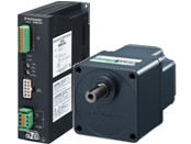
Gearhead / Motor / Control Circuit
This product is currently no longer available for sale
| Product Classification | Product Name | List Price | List Price | Shipping Date |
|---|---|---|---|---|
| Gearhead / Motor / Control Circuit | BLB590S-180S-1 | - | - | Discontinued Product (1.4.2017 discontinued) |
Included
- Motor, Gearhead, Control Circuit, Connection Cable, Connector for CN1 (3 pin), CN3 Connector (12 pin), Mounting Screws, Parallel Key, Operating Manual
Specifications
Other Specifications
Common Specifications
| Item | Specifications |
|---|---|
| Speed Setting Methods | Set the speed in the following way.
|
| Acceleration Time and Deceleration Time | 0.5~15 seconds: Time from stop to rated speed |
| Input Signals | Photocoupler Input Input Resistance: 5.1 kΩ Internal power supply voltage: 17 VDC±10% Connectable external power supply: 24 VDC -15~+20% 100 mA or more Sink/source input: supported via external wiring Forward input (FWD), Reverse input (REV), speed setting selection input (M0), alarm reset input |
| Output Signals | Photocoupler and open-collector output method External power supply: 30 VDC or less Alarm output 100 mA or less, speed output 10 mA or less Speed output, alarm output |
| Protective Functions * | When the following protective functions are activated, the motor will come to a coasting stop, and the alarm output will be turned OFF. The alarm LED of the driver will be blinking the number of times shown in parentheses.
|
| Maximum Extension Distance | 10.5 m between motor and driver |
| Time Rating | Continuous |
- * The BLB series cannot control the speed control of the motor in applications where the motor side is turned from the load side, such as gravitational operation.
When a load exceeding the permissible load inertia value is driven, or when gravitational operation is performed, the overvoltage protective function works to bring the motor to a coasting stop.
General Specifications
| Item | Motor | Driver | |
|---|---|---|---|
| Insulation Resistance | 100 MΩ or more when a 500 VDC megger is applied between the windings and the case after continuous operation under normal ambient temperature and humidity. |
After continuous operation at normal ambient temperature and humidity, the measurement value between the power supply terminal and the protective earth terminal and the power supply terminal and the I/O terminal is 100 MΩ min. using a 500 VDC megger. |
|
| Dielectric Strength | No abnormality is observed even with an application of 1.5 kVAC at 50 Hz between the coils and the case for 1 minute after continuous operation at normal ambient temperature and humidity. |
No abnormality is observed even with an application of 1834 VAC at 50 Hz between the power supply terminal and the protective earth terminal or 3 kVAC at 50 Hz between the power supply terminal and the signal I/O terminal for 1 minute after continuous operation at normal ambient temperature and humidity. |
|
| Temperature Rise | After continuous operation at normal ambient temperature and humidity, the temperature rise of the coil measured value by the thermocouple method is max. 65 °C and the measured value of the temperature rise of the case surface is max. 40 °C*1. |
After continuous operation at normal ambient temperature and humidity, the measurement value of the temperature rise of the heat sink is 50 °C max. using the thermocouple method. |
|
| Operating Environment | Ambient Temperature | 0~+50°C | |
| Ambient Humidity | 85 % max. (Non-condensing) | ||
| Altitude | Up to 1000 m above sea level | ||
| Atmosphere | No corrosive gases or dust Cannot be used in a radioactive area, magnetic field, vacuum, or other special environments. | ||
| Vibration | Not subject to continuous vibration or excessive shock In conformance with JIS C 60068-2-6, "Sine-wave vibration test method" Frequency Range: 10~55 Hz, Half Amplitude: 0.15 mm, Sweep Direction: 3 directions (X, Y, Z), Number of Sweeps: 20 times |
||
| Storage Conditions*2 | Ambient Temperature | -25~+70°C (Non-freezing) | |
| Ambient Humidity | 85 % max. (Non-condensing) | ||
| Altitude | Up to 3000 m above sea level | ||
| Thermal Class | EN Standards: 120 (E) | − | |
| Degree of Protection | IP65 (Excluding the installation surface of the round shaft type and connectors) | IP20 | |
- *1
- Attach round shaft types to a heat sink (Material: aluminum) of one of the following sizes to maintain a motor case surface temperature of 90 °C max.
10 W: 135x135 mm, 5 mm thickness 25 W: 165x165 mm, 5 mm thickness
40 W, 90 W: 200x200mm, 5mm thickness - *2
- The value for storage condition applies to short periods such as the period during transport.
Note
- Do not measure insulation resistance or perform a dielectric strength test the motor and driver are connected.
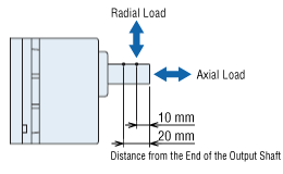
Permissible Radial Load and Permissible Axial Load
Combination type with a parallel shaft gearhead
| Product Name | Gear Ratio | Permissible Radial Load | Permissible Axial Load N |
|
|---|---|---|---|---|
| 10 mm From Shaft End N |
20 mm From Shaft End N |
|||
| BLB210■-□S-◇ | 3~15 | 50 | 80 | 30 |
| 30~180 | 120 | 180 | ||
| BLB425■-□S-◇ | 3~15 | 100 | 150 | 50 |
| 30~180 | 200 | 300 | ||
| BLB540■-□S-◇ | 3~15 | 250 | 350 | 100 |
| 30~180 | 300 | 450 | ||
| BLB590■-□S-◇ | 3~9 | 400 | 500 | 150 |
| 15 | 450 | 600 | ||
| 30~180 | 500 | 700 | ||
Round Shaft Type
| Product Name | Permissible Radial Load | Permissible Axial Load | |
|---|---|---|---|
| 10 mm From Shaft End N |
20 mm From Shaft End N |
||
| BLB210■-A-◇ | 70 | 100 | Half of the motor mass or less |
| BLB425■-A-◇ | 120 | 140 | |
| BLB540■-A-◇ BLB590■-A-◇ |
160 | 170 | |
System Configuration
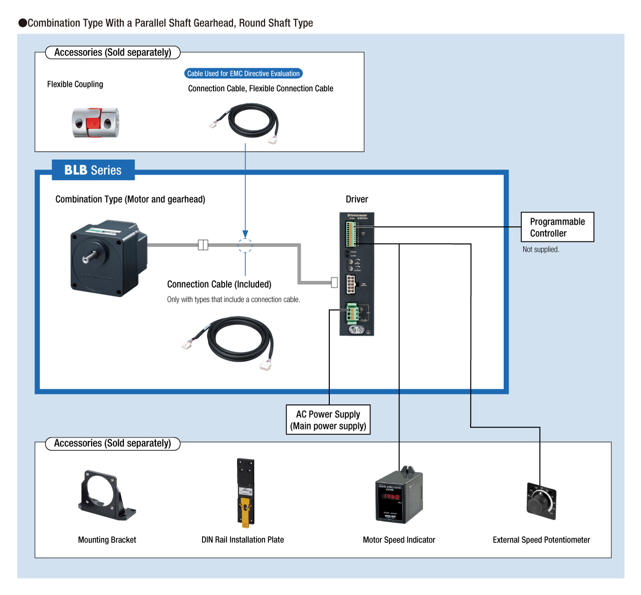
Cables and Accessories
close