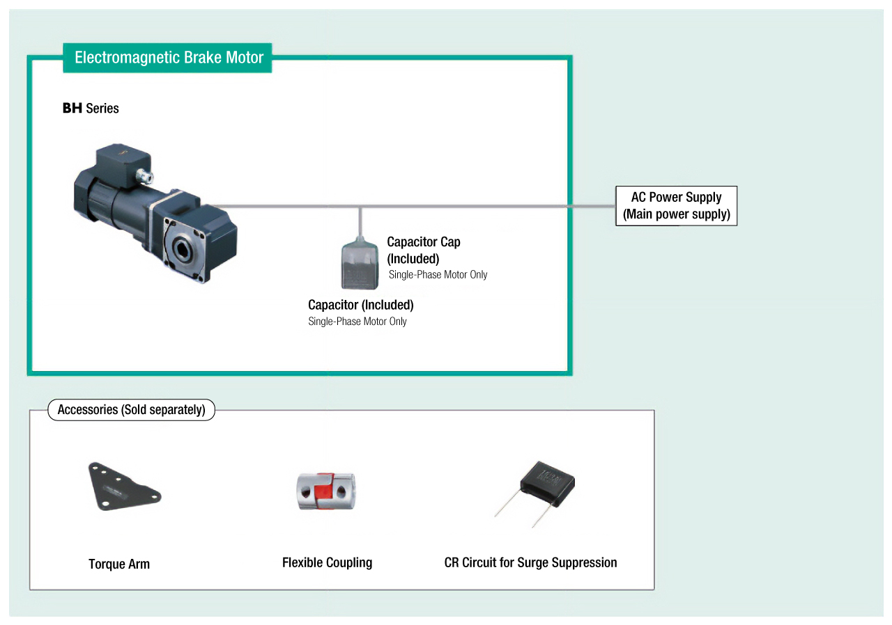
Electromagnetic Brake Motors
BHI62SMT-12.5RH

Combi geared motor
| Product Classification | Product Name | List Price | List Price | Shipping Date |
|---|---|---|---|---|
| Combi geared motor | BHI62SMT-12.5RH | SGD 876 | USD 701 | 16 Working Days |
• This product is subject to the Energy Efficiency Regulations in Thailand.
Included
- Motor: None
Gearhead: Parallel Key
Specifications
Characteristics
Starting and Braking Characteristics (Reference values)
Dimensions
Motor/Gearhead
Data Download
Other Specifications
General Specifications
| Item | Specifications |
|---|---|
| Insulation Resistance | After rated operation at normal ambient temperature and humidity, the measurement between the coils and the case is 100 MΩ min. using a 500 VDC megger. |
| Dielectric Strength | No abnormality is observed even with an application of 1.5 kVAC at 50 Hz between the coils and the case for 1 minute after rated operation at normal ambient temperature and humidity. |
| Temperature Rise | After a gearhead or equivalent heat sink*is connected for rated operation at normal ambient temperature and humidity, the measurement value of the winding temperature rise is 70 °C max. using the resistance change method. |
| Thermal Class | 130 (B) |
| Overheat Protective Device | Built-in thermal protector (automatic return type) Open: 150 ± 5 °C, Return: 96 ± 15 °C |
| Operating Ambient Temperature | Single-phase 100 V, single-phase 200 V, three-phase 200 V: -10~+50 °C (Non-freezing) Other voltages: -10~+40 °C (Non-freezing) |
| Operating Ambient Humidity | 85 % max. (Non-condensing) |
| Degree of Protection | IP54 (excluding mounting surface of the round shaft type) |
- *Heat Sink Size: 230 × 230 mm, 5 mm thickness (Material: Aluminum)
Permissible Radial Load and Permissible Axial Load of Gearhead
| Product Name | Gear Ratio | Maximum Permissible Torque N·m |
Permissible Radial Load N | Permissible Axial Load N |
|
|---|---|---|---|---|---|
| From Shaft End 10 mm |
From Shaft End 20 mm |
||||
| BH6G2-□ | 3~36 | 40 | 550 | 800 | 200 |
| 50~180 | 650 | 1000 | |||
| BH8G-□ | 30~180 | 70 | 1400 | 1700 | 400 |
| BH6G2-□RH | 5~36 | 60 | 1200* | 1100* | 300 |
| 50~180 | 2200* | 2000* | |||
| BH6G2-□RA | 5~36 | 60 | 900 | 1000 | 300 |
| 50~180 | 1700 | 1850 | |||
- *The permissible radial load is the value at the distance from the flange-mounting surface.

Calculating the Permissible Radial Load for Hollow Shaft Type
When the end of the load shaft being driven is not supported by a bearing as shown in the figure on the right, calculate the permissible radial load using the following formula. (This mechanism is the most demanding state in terms of radial load.)
Standards
Regulations and Standards Materials
Documents about compliance with regulations and standards can be downloaded from the "Data Download" tab on the product details page.
(The types of files available for download vary by product.)
Explanations of the Global Laws, Regulations and Standards can be found here.
Information about our compliance with safety standards for each of our product models can be found here.
Hazardous Substances
The product does not contain any substances (10 substances) exceeding the regulation values of the RoHS Directive (2011/65/EU, 2015/863/EU).
System Configuration