Stepper Motors RKII Series
RKS596MC-HS50
Geared Motor/Control Circuit
| Product Classification | Product Name | List Price | List Price | Shipping Date |
|---|---|---|---|---|
| Geared Motor / Control Circuit | RKS596MC-HS50 | SGD 2,305 | USD 1,844 | Product to be Discontinued (30.1.2026 order deadline) |
- *Please contact us regarding purchasing of product.
- *Product will be discontinued on 31.3.2026. Please place your order before the order deadline.
Included
- Motor, Control Circuit, Connector for Electromagnetic Brake Connection Terminals [CN1], Connector for Main Power Input Terminal, Connector for Pulse Input, I/O Signal Connector, Parallel Key
Specifications
Dimensions
Data Download
Other Specifications
Driver Specifications
| Built-in Controller Type | Pulse input type | |
|---|---|---|
| Maximum Input Pulse Frequency | − |
Line driver output by host controller: 500 kHz (at 50 % duty) Open-Collector Output by Host Controller: 250 kHz (at 50 % duty) Negative logic pulse input |
| Input Signals | Photocoupler Input, Input Signal Voltage: 11.4 V~26.4 V |
Photocoupler Input, Input Signal Voltage: 11.4 V~26.4 V (AWO, CS, FREE, ALM-RST) Photocoupler Input, Input Signal Voltage: 3 V~5.25 V (CW (PLS) +5 V, CCW (DIR) +5 V) Photocoupler Input, Input Signal Voltage: 21.6 V~26.4 V (CW (PLS) +24 V, CCW (DIR) +24 V) |
| Output Signals |
Photocoupler and Open-Collector Output External operating conditions: 30VDC 10 mA max. |
Photocoupler and Open-Collector Output External operating conditions: 30VDC 10 mA max. (READY, ALM, TIM) |
| Number of Positioning Data Sets | 64 Points | − |
| Positioning Operation | Independent, linked, linked 2, sequential, direct | − |
| Other operations | Continuous operation, JOG operation, return-to-home operation, Test Operation |
− |
| Control Module OPX-2A |
O | − |
| Support Software MEXE02 |
O | − |
General Specifications
| Motor | Driver | |||
|---|---|---|---|---|
| Built-in Controller Type | Pulse input type | |||
| Thermal Class | 130 (B) [UL is 105 (A) certified] |
− | ||
| Insulation Resistance |
100 MΩ or more when a 500 VDC megger is applied between the following places.
|
100 MΩ or more when a 500 VDC megger is applied between the following places.
|
||
| Dielectric Strength |
Sufficient to withstand the following for 1 minute:
|
Sufficient to withstand the following for 1 minute: | ||
|
|
|||
| Operating Environment (when operating) |
Ambient Temperature |
-10~+50 °C (Non-freezing): Standard Type TS/PS/FC geared type 0~+50 °C (Non-freezing): With encoder 0~+40 °C (Non-freezing): Harmonic Geared Type According to Oriental Motor’s measurement conditions |
0~+55 °C*2 (Non-freezing) | |
| Ambient Humidity | 85 % max. (Non-condensing) | |||
| Atmosphere | No corrosive gases or dust. No exposure to water, oil or other liquids. | |||
| Temperature Rise | 5-phase excitation at rated current, 80 °C max. at standstill Temperature rise of winding section at 80 °C or less (resistance change method) |
− | ||
| Degree of Protection | IP20 | IP10 | IP20 | |
| Stop position accuracy*3 | ±3 arc minute (±0.05˚) | |||
| Shaft Runout | 0.05 T.I.R. (mm)*4 | − | ||
| Radial Play*5 | 0.025 mm Max. (Load 5 N) | − | ||
| Axial Play*6 | 0.075 mm Max. (Load 10 N) | − | ||
| Concentricity of Installation Pilot to the Shaft |
0.075 T.I.R. (mm)*4 | − | ||
| Perpendicularity of mounting surface to the shaft |
0.075 T.I.R. (mm)*4 | − | ||
- *1
- (Only for types with electromagnetic brake)
- *2
- When a heat sink of a capacity at least equivalent to an aluminum plate with a size of 200×200 mm and 2 mm thickness
- *3
- 0.72˚ is the value under no load. (The value changes with the size of the load.)
- *4
- T.I.R. (Total Indicator Reading): The total dial gauge reading when the measurement section is rotated 1 revolution centered on the reference axis center.
- *5
- Radial Play: Displacement in shaft position in the radial direction when a 5 N load is applied perpendicular to the tip of the motor shaft.
- *6
- Axial Play: Displacement in shaft position in the axial direction when a 10 N load is applied to the motor shaft in the axial direction.
Note
- Disconnect the motor and driver when measuring insulation resistance, or conducting a dielectric strength test.
Rotation Direction
This indicates the rotation direction when viewed from the output shaft side.
The rotation direction of the gearhead output shaft relative to the standard type motor output shaft varies depending on the gear type and gear ratio. Please check the following table.
| Type | Gear Ratio | Rotation Direction as Viewed From the Motor Output Shaft Side |
|---|---|---|
| TS Geared Type | 3.6, 7.2, 10 | Same direction |
| 20, 30 | Opposite direction | |
| TH Geared Type Frame size 28 mm |
7.2, 10 | Opposite direction |
| 20, 30 | Same direction | |
| TH Geared Type Frame size 42 mm, 60 mm, 90 mm |
3.6, 7.2, 10 | Same direction |
| 20, 30 | Opposite direction | |
| SH Geared Type Frame size 28 mm |
7.2, 36 | Same direction |
| 9, 10, 18 | Opposite direction | |
| SH Geared Type Frame size 42 mm, 60 mm |
3.6, 7.2, 9, 10 | Same direction |
| 18, 36 | Opposite direction | |
| SH Geared Type Frame size 90 mm |
3.6, 7.2, 9, 10, 18 | Same direction |
| 36 | Opposite direction | |
| CS Geared Type | 5, 10, 15, 20 | Same direction |
|
FC Geared Type PS Geared Type PN Geared Type HPG Geared Type |
Overall gear ratio | Same direction |
| Harmonic Geared Type | 50, 100 | Opposite direction |
Permissible Radial Load and Permissible Axial Load
Unit: N
| Type | Motor Frame Size |
Type | Gear Ratio | Permissible Radial Load | Permissible Axial Load | ||||
|---|---|---|---|---|---|---|---|---|---|
| Distance From Shaft End [mm] | |||||||||
| 0 | 5 | 10 | 15 | 20 | |||||
| Standard Type | 42 mm | PKE54 | − | 35 | 44 | 58 | 85 | − | 15 |
| 60 mm | PKE56 | 90 | 100 | 130 | 180 | 270 | 30 | ||
| 85 mm | PKE59 | 260 | 290 | 340 | 390 | 480 | 60 | ||
| TS Geared Type | 42 mm | PKE54 | 3.6, 7.2, 10 | 20 | 30 | 40 | 50 | − | 15 |
| 20, 30 | 40 | 50 | 60 | 70 | − | ||||
| 60 mm | PKE56 | 3.6, 7.2, 10 | 120 | 135 | 150 | 165 | 180 | 40 | |
| 20, 30 | 170 | 185 | 200 | 215 | 230 | ||||
| 90 mm | PKE59 | 3.6, 7.2, 10 | 300 | 325 | 350 | 375 | 400 | 150 | |
| 20, 30 | 400 | 450 | 500 | 550 | 600 | ||||
| PS Geared Type | 42 mm | PKE54 | 5 | 70 | 80 | 95 | 120 | - | 100 |
| 7.2 | 80 | 90 | 110 | 140 | - | ||||
| 10 | 85 | 100 | 120 | 150 | - | ||||
| 25 | 120 | 140 | 170 | 210 | - | ||||
| 36 | 130 | 160 | 190 | 240 | - | ||||
| 50 | 150 | 170 | 210 | 260 | - | ||||
| 60 mm | PKE56 | 5 | 170 | 200 | 230 | 270 | 320 | 200 | |
| 7.2 | 200 | 220 | 260 | 310 | 370 | ||||
| 10 | 220 | 250 | 290 | 350 | 410 | ||||
| 25 | 300 | 340 | 400 | 470 | 560 | ||||
| 36 | 340 | 380 | 450 | 530 | 630 | ||||
| 50 | 380 | 430 | 500 | 600 | 700 | ||||
| 90 mm | PKE59 | 5 | 380 | 420 | 470 | 540 | 630 | 600 | |
| 7.2 | 430 | 470 | 530 | 610 | 710 | ||||
| 10 | 480 | 530 | 590 | 680 | 790 | ||||
| 25 | 650 | 720 | 810 | 920 | 1070 | ||||
| 36 | 730 | 810 | 910 | 1040 | 1210 | ||||
| 50 | 820 | 910 | 1020 | 1160 | 1350 | ||||
| Harmonic Geared Type | 42 mm | PKE54 | 50, 100 | 180 | 220 | 270 | 360 | 510 | 220 |
| 60 mm | PKE56 | 320 | 370 | 440 | 550 | 720 | 450 | ||
| 90 mm | PKE59 | 1090 | 1150 | 1230 | 1310 | 1410 | 1300 | ||
| FC Geared Type | 42 mm | PKE54 | 7.2, 10, 20, 30 | 180 | 200 | 220 | 250 | - | 100 |
| 60 mm | PKE56 | 270 | 290 | 310 | 330 | 350 | 200 | ||
- The product names are listed such that the product names are distinguishable.
-
The PS Geared Type has a lifetime of 20,000 hours, when either the permissible radial load or the permissible axial load is applied.
Click here for information about gearhead life
Radial Load and Axial Load
Electromagnetic Brake Specifications
| Product Name | PKE54 | PKE56 | PKE59 |
|---|---|---|---|
| Type | Power off activated type | ||
| Power Supply Voltage | 24 VDC ±5 %* | ||
| Power Supply Current [A] | 0.08 | 0.25 | 0.42 |
| Time Rating | Continuous | ||
- *For the type with an electromagnetic brake, a 24 VDC ±4 % specification applies if the wiring distance between the motor and the driver is extended by 15 m using a cable.
- The product names are listed such that the product names are distinguishable.
Standards
Regulations and Standards Materials
Documents about compliance with regulations and standards can be downloaded from the "Data Download" tab on the product details page.
(The types of files available for download vary by product.)
Explanations of the Global Laws, Regulations and Standards can be found here.
Information about our compliance with regulations and standards for each of our product series can be found here.
Hazardous Substances
The product does not contain any substances (10 substances) exceeding the regulation values of the RoHS Directive (2011/65/EU, 2015/863/EU).
System Configuration
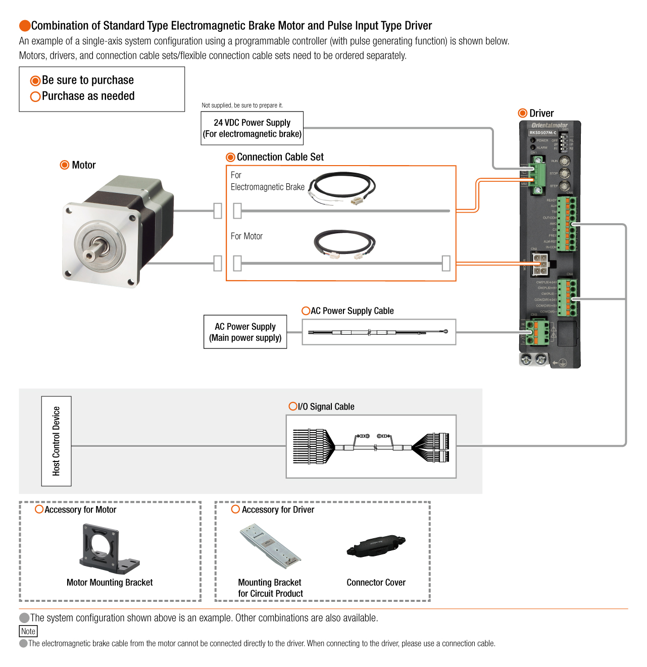
Cables and Accessories