AC Speed Control Motors MSS Series
MSS003-003
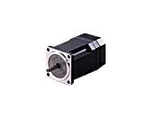
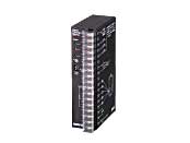
Motor/Control Circuit
This product is currently no longer available for sale
| Product Classification | Product Name | List Price | List Price | Shipping Date |
|---|---|---|---|---|
| Motor / Control Circuit | MSS003-003 | SGD 355 | USD 284 | Discontinued Product (31.3.2020 discontinued) |
Included
- Speed Control Motor and Controller Package: Motor, Control Circuit, External Speed Potentiometer, Mounting Bracket for Control Circuit (with Screws), Operating Manual
Specifications
Other Specifications
Common Specifications of the Circuit Section
| Item | MSP101 |
|---|---|
| Power Supply Input | Single-Phase 100 VAC±10% 50/60 Hz |
| Functions | Speed control, no-contact instantaneous stop, no-contact bidirectional rotation, no-contact rotation speed switching, self-test |
| Control Power Supply | 24 VDC±10 % or 5 VDC±10 % min. 0.1 A |
| Input Signals | Photocoupler Input External Contact Capacity: 26.4 VDC 40 mA CW/CCW/FREE/SPEED SET |
| Speed Setting Methods | Set 1 method from the following.
|
General Specifications
| Item | Motor | Speed Controller | |
|---|---|---|---|
| Insulation Resistance | After rated operation at normal ambient temperature and humidity, the measurement between the coils and the case is 50 MΩ min. using a 500 VDC megger. | After rated operation at normal ambient temperature and humidity, the value measured between the power supply input terminal and FG, between the signal input terminal and FG, and between the power supply input terminal and signal input terminal by a 500 VDC megger is min. 100 MΩ. | |
| Dielectric Strength | No abnormality is observed even with an application of 1 kVAC at 50 Hz between the coils and the case for 1 minute after rated operation at normal ambient temperature and humidity. | After rated operation at normal ambient temperature and humidity, no abnormality is observed even if 50 Hz, 1.5 kVAC is applied between the power supply input terminal and FG, between the signal input terminal and FG, or between the power supply input terminal and signal input terminal for 1 minute. | |
| Temperature Rise | After no-load rated operation at normal ambient temperature and humidity, the motor surface temperature rise measured by the thermometer method is 60 °C max. | - | |
| Operating Environment | Ambient Temperature | -10~+50°C (Non-freezing) | 0∼+40°C (Non-freezing) |
| Ambient Humidity | 85 % max. (Non-condensing) | ||
| Thermal Class | 120(E) | - | |
Note
-
Do not perform an insulation resistance measurement or a dielectric strength test while the motor and speed controller are connected.
Permissible Radial Load and Permissible Axial Load of Round Shaft Type
Permissible Radial Load
| Motor | Permissible Radial Load N | ||
|---|---|---|---|
| Frame Size □ (mm) | Output Shaft Diameter φ (mm) | From Shaft End 10 mm |
From Shaft End 20 mm |
| 42 | 5 | 40 | - |
| 60 | 6 | 50 | 110 |
| 70 | 6 | 40 | 60 |
| 80 | 8 | 90 | 140 |
| 90 | 10 | 140 | 200 |
| 12 | 240 | 270 | |
Permissible Axial Load
Avoid axial load as much as possible. If an axial load is unavoidable, keep it at half or less of the motor mass.

System Configuration
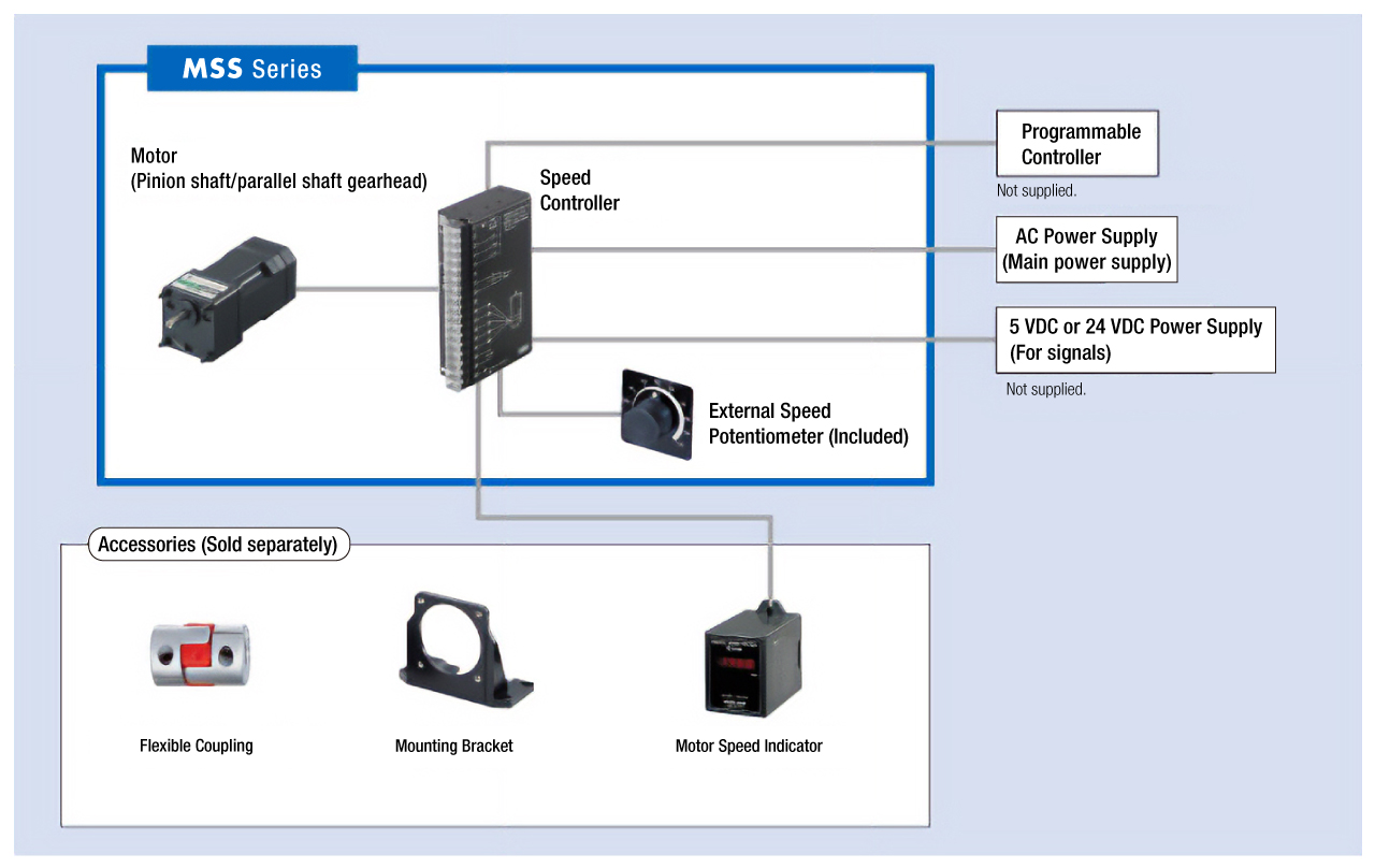
Cables and Accessories
close