AC Speed Control Motors MSC Series
MSCI315JC-150-3
Gearhead / Motor / Control Circuit
This product is currently no longer available for sale
| Product Classification | Product Name | List Price | List Price | Shipping Date |
|---|---|---|---|---|
| Gearhead / Motor / Control Circuit | MSCI315JC-150-3 | - | - | Discontinued Product (1.4.2017 discontinued) |
Included
- Motor, Gearhead, Control Circuit, Capacitor, Capacitor Cap, Mounting Screws, Connection Cable, Parallel Key, Operating Manual
Specifications
Characteristics
Other Specifications
Control Circuit Specifications
| Item | Specifications |
|---|---|
| Power Supply Voltage | Single-Phase 100/110/115 VAC±10% Single-Phase 200/220/230 VAC±10% |
| Power Supply Frequency | 50/60 Hz |
| Applicable Speed Controls Motor Output Power |
6 W, 15 W, 25 W, 40 W, 60 W, 90 W |
| Variable Speed Range | 50Hz: 90~1400r/min 60Hz: 90~1600r/min |
| Functions | Speed control, no-contact instantaneous stop, no-contact bidirectional rotation, no-contact rotation speed switching, slow start/slow down (0.3~15 seconds: at 1000 r/min no load) |
| Speed Setting Methods |
Set the speed in the following way.
|
| Control Power Supply | 24 VDC±10 % min. 100 mA |
| Input Signals | Photocoupler Input Input resistance: 4.7 kΩ FWD, REV, INT/EXT, ALARM-RESET |
| Output Signals | Open-collector output max. 30 VDC SPEED-OUT: max. 10 mA, ALARM-OUT: max. 40 mA |
| Protective Functions |
When the following protective functions are activated, the motor will coast to a stop, and the ALARM output will be turned off.
|
General Specifications
| Item | Motor | Speed Controller | |
|---|---|---|---|
| Insulation Resistance | 100 MΩ or more when a 500 VDC megger is applied between the windings and the case after continuous operation under normal ambient temperature and humidity. |
100 MΩ min. when a 500 VDC megger is applied between the main circuit terminal and the control circuit terminal, between the main circuit terminal and the case, and between the main circuit terminal and FG after continuous operation under normal ambient temperature and humidity. |
|
| Dielectric Strength | No abnormality is observed when 1.5 kVAC at 50 Hz or 60 Hz applied between the coils and case for 1 minute after continuous operation under normal ambient temperature and humidity. |
No abnormality is observed when 1.9 kVAC is applied at 50 Hz or 60 Hz between the main circuit terminal and the control circuit terminal and between the main circuit terminal and the case, and when 1.5 kVAC is applied at 50 Hz or 60 Hz between the main circuit terminal and FG, for 1 minute after continuous operation under normal ambient temperature and humidity. |
|
| Temperature Rise | A gearhead or equivalent heat sink * is connected to the motor, and the winding temperature rise is measured at 80 °C max. using the resistance change method after continuous operation with no load under normal ambient temperature and humidity. |
- | |
| Overheat Protective Device | MSCI26 Type is impedance-protected All other motors have a built-in thermal protector (automatic return type) Open: 130±5℃, Reset: 85±20℃ |
- | |
| Operating Environment | Ambient Temperature | Single-Phase 100 V, 200 V: -10~+50°C (Non-freezing) Single-Phase 100/115 V, 200/230 V: -10~+40°C (Non-freezing) |
0∼+50°C (Non-freezing) |
| Ambient Humidity | 85 % max. (Non-condensing) | ||
| Altitude | Up to 1000 m above sea level | ||
| Thermal Class | 130(B) | - | |
| Degree of Protection | IP20 | IP20 | |
- *Heat Sink Size (Material: Aluminum)
| Motor Output Power | Size (mm) | Thickness (mm) |
|---|---|---|
| 6 W | 115x115 | 5 |
| 15 W | 125x125 | |
| 25 W | 135x135 | |
| 40 W | 165x165 | |
| 60 W | 200x200 | |
| 90 W | 200x200 |
Note
- Do not measure insulation resistance or perform a dielectric strength test while the motor and speed controller are connected.
Permissible Radial Load and Permissible Axial Load
| Product Name | Gear Ratio | Permissible Radial Load | Permissible Axial Load N |
|
|---|---|---|---|---|
| 10 mm From Shaft End N |
20 mm From Shaft End N |
|||
| MSCI26 ■-□◇ | 5~25 |
150 | 200 | 40 |
| 30~360 | 200 | 300 | ||
| MSCI315 ■-□◇ | 5~25 |
200 | 300 | 80 |
| 30~360 | 300 | 400 | ||
| MSCI425 ■-□◇ | 5~25 |
300 | 350 | 100 |
| 30~360 | 450 | 550 | ||
| MSCI540
■-□◇ MSCI560 ■-□◇ |
5~9 |
400 | 500 | 150 |
| 12.5~18 | 450 | 600 | ||
| 25~300 | 500 | 700 | ||
| MSCI590 ■-□◇ | 5~9 |
400 | 500 | 150 |
| 12.5~18 | 450 | 600 | ||
| 25~180 | 500 | 700 | ||
System Configuration
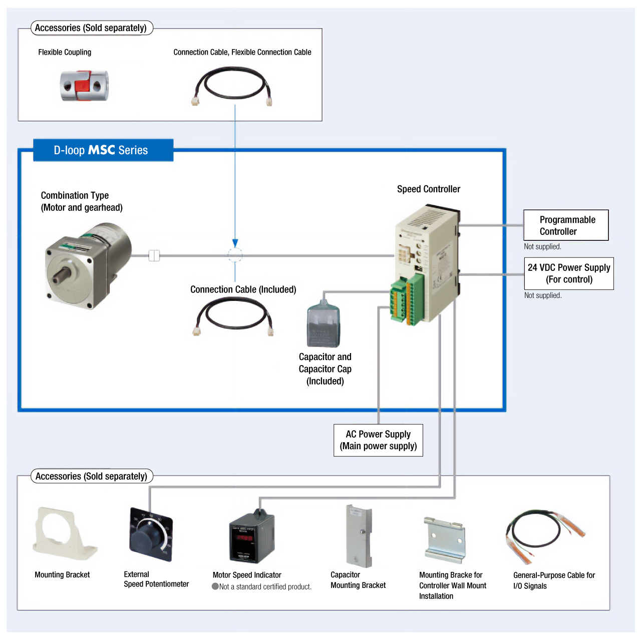
Cables and Accessories
close
close