Rack-and-Pinion System LBE Series
LBE4F300MC-10-1

Rack and Pinion Motor/Control Circuit
| Product Classification | Product Name | List Price | List Price | Shipping Date |
|---|---|---|---|---|
| Rack and Pinion Motor / Control Circuit | LBE4F300MC-10-1 | SGD 1,266 | USD 1,013 | Discontinued Product (31.3.2024 discontinued) |
Included
- Rack and Pinion Motor, Control Circuit, Connection Cable (1 m), External Speed Potentiometer (with Signal Line), Operating Manual
Specifications
Other Specifications
General Specifications
| Item | Rack and Pinion Motor Part | Driver | |
|---|---|---|---|
| Insulation Resistance | 100 MΩ or more when a 500 VDC megger is applied between the windings and the case after continuous operation under normal ambient temperature and humidity. | After continuous operation at normal ambient temperature and humidity, the measured value using a 500 VDC megger is 100 MΩ min. between the power supply terminal and the protective earth terminal and the power supply terminal and the I/O terminal. | |
| Dielectric Strength | After continuous operation at normal ambient temperature and humidity, no abnormality is observed even when 50 Hz, 1.5 kVAC is applied between the windings and the case for 1 minute. | No abnormality is observed even with an application of 1834 VAC at 50 Hz between the power supply terminal and the protective earth terminal or 3 kVAC at 50 Hz between the power supply terminal and the I/O terminal for 1 minute after continuous operation at normal ambient temperature and humidity. | |
| Temperature Rise | After continuous operation at normal ambient temperature and humidity, the measured value using the thermocouple method is 50 °Cmax. for the temperature rise of the coils and 40 °C max. for the temperature rise on the case surface. | After continuous operation at normal ambient temperature and humidity, the measurement value of the temperature rise of the heat sink is 50 °C max. using the thermocouple method. | |
| Operating Environment | Ambient Temperature | 0~+50 °C | |
| Ambient Humidity | 85 % max. (Non-condensing) | ||
| Altitude | Less than 1000 m above sea level | ||
| Atmosphere | Cannot be used in special environments such as corrosive gas, no dust, radioactive materials, magnetic fields, or vacuums | ||
| Vibration | Not subject to continuous vibration or excessive shock In conformance with JIS C 60068-2-6, "Sine-wave vibration test method" Frequency Range: 10∼55 Hz, Half Amplitude: 0.15 mm Sweep Direction: 3 directions (X, Y, Z) Number of Sweeps: 20 times |
||
| Storage Conditions* | Ambient Temperature | −25~+70 °C (non-freezing) | |
| Ambient Humidity | 85 % max. (Non-condensing) | ||
| Altitude | Up to 3000 m above sea level | ||
| Insulation Class | EN Standards: E Class (120 °C) | - | |
- *The value for storage condition applies to short periods such as the period during transport.
Note
- Do not measure insulation resistance or perform the dielectric strength test while the rack and pinion motor and the driver are connected.
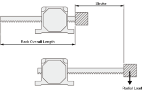
Rack Permissible Rotational Torque (Moment)
The rotational torque applied to the rack should be less than the value shown in the table below.
| Product Name | Rack Permissible Rotational Torque (Moment) |
|---|---|
| LBE2 type | 0.3 N·m max. |
| LBE4 type | 0.5 N·m max. |
- Be sure to keep rotational torque below the permissible value. If too much rotational torque is applied, the abrasion of rack bushings will be sped up.
Maximum Radial Load
| Stroke mm |
Maximum Radial Load N |
|||
|---|---|---|---|---|
| LBE2□90 | LBE2□300 | LBE4□50 | LBE4□300 | |
| 100 | 25 | 25*1 | 120 | 60*1 |
| 200 | 20 | 10*1 | 90 | 40*1 |
| 300 | 10 | 10*1 | 70 | 30*1 |
| 400 | 10 | 10*1 | 60 | 25*1 |
| 700 | - | - | 40 | 10*1 |
| 800 | *2 | *2 | - | - |
| 1000 | - | - | 15 | *2 |
- *1
- Use an operating speed of 90 mm/s max. Do not apply a radial load when using in more than 90 mm/s.
Also, an external guide must be installed. - *2
- Do not apply a radial load. An external guide must be installed.
- Either
F orB indicating the rack moving direction is entered where the box □ is located within the product name.
Common Specifications Circuit Section
| Product Name | BLED3AM | BLED6AM | BLED3CM | BLED6CM | BLED3SM | BLED6SM | |
|---|---|---|---|---|---|---|---|
| Power Supply Input | Rated Voltage V | Single-Phase 100-120 | Single-Phase 200-240 | Three-Phase 200-240 | |||
| Permissible Voltage Range | −15~+10 % | ||||||
| Rated Frequency Hz | 50/60 | ||||||
| Permissible Frequency Range | ±5 % | ||||||
| Rated Input Current A | 1.3 | 2.0 | 0.8 | 1.2 | 0.45 | 0.7 | |
| Maximum Input Current A | 3.5 | 4.5 | 2.1 | 2.6 | 1.2 | 1.5 | |
Common Specifications Operation Specifications
-
Standard Model:This specification applies when the basic rack and pinion motor and driver package is used.
-
Extended Functions:These specifications apply when the separately sold data setter (OPX-2A) is used.
| Item | Standard Model | Extended Functions |
|---|---|---|
| Rack Speed Setting Method |
Set 1 method from the following.
|
Set 1 method from the following.
|
| Acceleration Time and Deceleration Time | Setting by Acceleration/deceleration Time Potentiometer: 0.2~15 seconds. |
Set 1 method from the following.
|
| Multi-Speed Setting Methods | 2 Speeds: 1 speed set by the internal speed potentiometer and 1 speed set by the external speed potentiometer (20 kΩ, 1/4 W) or external DC voltage (0~5 VDC or 0~10 VDC) |
Set 1 method from the following.
|
| Input Signals | Photocoupler Input Input Resistance: 5.1 kΩ Operated by Internal Power Supply: 17 VDC±10% Connectable external DC power supply: 24 VDC -15∼+20% current 100 mA min. |
|
| Forward input (FWD), Reverse input (REV), Stop mode selection input (STOP-MODE), Speed setting selection input (M0), Alarm reset input (ALARM-RESET), Electromagnetic brake release input (MB-FREE), Regeneration resistor thermal input (TH) |
Arbitrary signal assignment to general purpose input X0∼X6 (7 points) is possible Forward input (FWD), Reverse input (REV), Stop mode selection input (STOP-MODE), Speed Setting Selection Input (M0, M1, M2), Alarm reset input (ALARM-RESET), Electromagnetic brake release input (MB-FREE), Regeneration resistor thermal input (TH), External error input (EXT-ERROR) |
|
| Output Signals | Open-Collector Output External Operating Condition: Voltage Control 4.5∼30.0 VDC Current 40 mA max. Speed Output: 5 mA min. |
|
| Speed output (SPEED-OUT), Alarm output 1 (ALARM-OUT 1) |
Arbitrary signal assignment to general purpose output Y0, Y1 (2 points) is possible. Speed output (SPEED-OUT), Alarm output 1 (ALARM-OUT 1), Motor running output (MOVE), Speed Attainment Output (VA), Alarm output 2 (ALARM-OUT 2), Warning output (WNG), Torque limiting output (TLC) |
|
| Protective Function | Overload, sensor error, sensor error at power-on, overvoltage, undervoltage, overspeed, overcurrent, EEPROM error, regeneration resistor overheat, External stop*2, prevention of operation at power-on*3, main circuit output error*4 |
|
| Maximum Extension Distance | 20.4 m between motor and driver | |
| Time Rating | Continuous | |
- *1
- This is a 1-speed set by the internal speed potentiometer and 1-speed set by external speed potentiometer (20 kΩ, 1/4 W) or external DC voltage (0~5 VDC or 0~10 VDC).
- *2
- This function is available only when EXT-ERROR is assigned by using control module (OPX-2A).
- *3
- Occurs only when using control module (OPX-2A) , and setting is effective.
- *4
- Not occur when using control module (OPX-2A) , and setting the torque limiting value less than 200 %.
Torque Limiting Function
Using data setter (OPX-2A) sold separately, allows setting limit on output torque of rack and pinion motor.
| Item | Specifications |
|---|---|
| Torque Limiting Setting Methods |
Set 1 method from the following.
|
| Torque Limiting Setting Range |
Assuming that the rated torque of the motor is 100 %, torque limiting values can be set in the following ranges (Initial value 200 %).
|
Note
- An error of approximately ±20 % maximum may occur between the setting value and generated torque due to the setting speed, power supply voltage, or motor cable extension distance.
Push Force (Reference Value)
Push force can be set in data mode and torque limiting value using the control module (OPX-2A) sold separately.

Note
- The above are reference values for horizontal operation. These are not guaranteed values.
- For applications in the vertical direction, an external force equal to (load mass + rack mass) × gravitational acceleration will be applied, so the relationship between the external force and the thrust must be considered.
When using this product, measure the actual push force and set the torque limiting value. - Push-motion operation should be performed within the conditions of the push force (rack speed and torque limiting value). If these conditions are exceeded, the rack may be stopped, and the motor may be damaged.
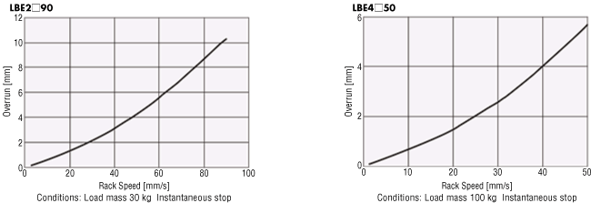
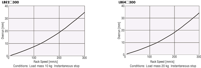
Overrun (Reference value)
The overrun amount varies depending on the rack speed and load mass. Please check the operating conditions before use.
- Either F or B indicating the rack moving direction is entered where the box □ is located within the product name.
A number indicating the stroke is entered where the box ■ is located within the product name.
Standards
Regulations and Standards Materials
Documents about compliance with regulations and standards can be downloaded from the "Data Download" tab on the product details page.
(The types of files available for download vary by product.)
Explanations of the Global Laws, Regulations and Standards can be found here.
Information about our compliance with regulations and standards for each of our product series can be found here.
Hazardous Substances
The product does not contain any substances (10 substances) exceeding the regulation values of the RoHS Directive (2011/65/EU, 2015/863/EU).
System Configuration