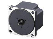
Brushless Motors BLH Series
BLHM5100K-GFS+GFS5G30+BLHD100K
| Product Classification | Product Name | List Price | List Price | Shipping Date |
|---|---|---|---|---|
| Motor | BLHM5100K-GFS | SGD 258 | USD 206 | 3 Working Days |
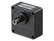
| Gearhead | GFS5G30 | SGD 214 | USD 171 | 3 Working Days |
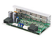
| Control Circuit | BLHD100K | SGD 198 | USD 158 | 7 Working Days |
Included
- Motor: None
Gearhead: Mounting Screws, Parallel Key
Control Circuit: Power Supply Cable and I/O Signal Cable Set (0.3 m)
Specifications
Characteristics
Dimensions
Data Download
Other Specifications
General Specifications
| Item | Motor | Driver | |
|---|---|---|---|
| Insulation Resistance | 100 MΩ or more when a 500 VDC megger is applied between the windings and the case after continuous operation under normal ambient temperature and humidity. |
After continuous operation at normal ambient temperature and humidity, the value measured with a 500 VDC megger between the power supply input and the heat sink is min. 100 MΩ. |
|
| Dielectric Strength | No abnormality is observed even with an application of 1.5 kVAC at 50 Hz between the coils and the case for 1 minute after continuous operation at normal ambient temperature and humidity. |
After continuous operation at normal ambient temperature and humidity, the value measured with a 500 VDC megger between the power supply input and the heat sink is min. 100 MΩ. (Except for RS-485 communication type) |
|
| Temperature Rise | After continuous operation at normal ambient temperature and humidity, the measured value using the thermocouple method is 50 °Cmax. for the temperature rise of the coils and 40°C*1 max. for the temperature rise on the case surface. |
After continuous operation at normal ambient temperature and humidity, the measurement value of the temperature rise of the heat sink is 50 °C max. using the thermocouple method. |
|
| Operating Environment | Ambient Temperature | 0∼+50°C (Non-freezing) | |
| Ambient Humidity | 85 % max. (Non-condensing) | ||
| Altitude | Up to 1000 m above sea level | ||
| Atmosphere | No corrosive gases or dust Should not be exposed to water or oil. Cannot be used in a radioactive area, magnetic field, vacuum, or other special environments. |
||
| Vibration | Must not be subjected to continuous vibration or excessive shock. Conforms to JIS C 60068-2-6, "Sine-wave vibration test method." Frequency Range: 10~55 Hz, Half Amplitude: 0.15 mm Sweep direction: 3 directions (X, Y, Z) Number of sweeps: 20 |
||
| Storage Condition*2 | Ambient Temperature | -25~+70°C (Non-freezing) Electromagnetic Brake Motor: -20~+70°C (Non-freezing) |
-25~+70°C (Non-freezing) |
| Ambient Humidity | 85 % max. (Non-condensing) | ||
| Altitude | Up to 3000 m above sea level | ||
| Atmosphere | No corrosive gases or dust Should not be exposed to water or oil. Cannot be used in a radioactive area, magnetic field, vacuum, or other special environments. |
||
| Thermal Class | UL/CSA Standards: 105 (A), EN Standards: 120 (E) | − | |
| Degree of Protection | Connector Type/Lead Wire Type IP40 Cable Type, Electromagnetic Brake Motor: IP65 excluding the connector section and the round shaft type mounting surface) |
IP00 | |
- *1
- Attach round shaft types to a heat sink (Material: aluminum) of one of the following sizes to maintain a motor case surface temperature of 90 °C max. (Except BLHM015.)
Heat Sink Size
| Product Name | Size (mm) | Thickness (mm) |
|---|---|---|
| BLM015, BLM030, BLM230, BLHM230 | 115x115 | 5 |
| BLM250, BLM 450, BLHM450 | 135x135 | |
| BLHM5100 | 200x200 |
- *2
- The value for storage condition applies to short periods such as the period during transport.
Note
- Do not measure insulation resistance or perform a dielectric strength test the motor and driver are connected.
Common Specifications
| Item | Specifications | ||||
|---|---|---|---|---|---|
| Driver Type | Analog Setting Type | Digital Setting Type | RS-485 Communication Type | ||
| Data Setting Number | 2-Speed | 8-Speed | 8-Speed | ||
| Rotation Speed | Control Range | 100~3000 r/min | 80~3000 r/min | 80~3000 r/min | |
| Setting Method |
|
|
|
||
| Acceleration Time and Deceleration Time |
Setting Range | 15 W, 30 W, 50 W: 0.1~12.0 seconds 100 W: 0.5~10 seconds Acceleration time and deceleration time are common settings |
0.1∼15.0 seconds | 0.1∼15.0 seconds | |
| Setting Method |
|
|
|
||
| Torque Limiting*1 | Setting Range | − | 0~200% | 0~200% | |
| Setting Method |
|
|
|||
| I/O function | Direct Input | Method | C-MOS Negative Logic Input | C-MOS Negative Logic Input | C-MOS Negative Logic Input |
| Points | 5 Points | 6 Points | 5 Points | ||
| Initial Distribution | 15 W, 30 W, 50 W: START/STOP, RUN/BRAKE, FWD/REV, M0, ALM-RST 100 W: START/STOP, RUN/BRAKE, CW/CCW, INT.VR/EX, ALARM-RESET |
START/STOP, RUN/BRAKE, FWD/REV, M0, M1, ALM-RST |
START/STOP, RUN/BRAKE, FWD/REV, M0, ALM-RST |
||
| Direct Output | Method | Transistor Open-Collector Output | Transistor Open-Collector Output | Transistor Open-Collector Output | |
| Points | 2 Points | 4 Points | 2 Points | ||
| Initial Distribution | 15 W, 30 W, 50 W: SPEED-OUT, ALM-B 100 W: SPEED, ALARM |
SPEED-OUT, ALM-B, TLC, DIR | SPEED-OUT, ALM-B | ||
| RS-485 Communication Remote Input | − | − | 16 Points | ||
| RS-485 Communication Remote Output | − | − | 16 Points | ||
| Setting Tool | Support Software MEXE02 | − | ○ | ○ | |
| Information | − | ○ | ○ | ||
| Alarm*2 | ○ | ○ | ○ | ||
| Maximum Extension Distance | 15 W, 30 W, 50 W: 5 m between motor and driver [When using connection cable (sold separately)] 100 W: 2 m between motor and driver [When using connection cable (sold separately)] |
||||
| Time Rating | Continuous | ||||
- *1
- The torque limiting will cause an error with a maximum of ±20 % (at rated torque and rated speed) between the setting value and the generated torque, depending on the setting speed, power supply voltage, and motor cable extension distance.
- *2
- The BLH Series cannot control the speed control of the motor in applications where the motor side is turned from the load side, such as gravitational operation. The protective function works to bring the motor to a coasting stop when driving a load that exceeds the permissible inertia value or during gravitational operation.
Permissible Radial Load and Permissible Axial Load
Parallel Shaft Gearhead
| Output | Gear Ratio | Permissible Radial Load |
Permissible Axial Load N |
|
|---|---|---|---|---|
|
10 mm From Shaft End N |
20 mm From Shaft End N |
|||
| 15 W | 5, 10, 15, 20 30, 50, 100 |
50 | − | 30 |
| 30 W | 5 | 100 | 150 | 40 |
| 10, 15, 20 | 150 | 200 | ||
| 30, 50, 100, 200 | 200 | 300 | ||
| 50 W | 5 | 200 | 250 | 100 |
| 10, 15, 20 | 300 | 350 | ||
| 30, 50, 100, 200 | 450 | 550 | ||
| 100 W | 5 | 300 | 400 | 150 |
| 10, 15, 20 | 400 | 500 | ||
| 30, 50, 100, 200 | 500 | 650 | ||
CS Geared Motor
| Output | Gear Ratio | Permissible Radial Load |
Permissible Axial Load N |
|
|---|---|---|---|---|
|
10 mm From the End of the Output Shaft N |
20 mm From the End of the Output Shaft N |
|||
| □42mm-15 W □42mm-30 W |
5 | 50 | - | 40 |
| 10, 15, 20 | 80 | - | ||
| □60mm-30 W □60mm-50 W |
5 | 150 | 190 | 70 |
| 10, 15, 20 | 200 | 260 | ||
Hollow Shaft Flat Gearhead
| Output | Gear Ratio | Permissible Radial Load |
Permissible Axial Load N |
|
|---|---|---|---|---|
|
10 mm From the Gearhead Mounting Surface N |
20 mm From the Gearhead Mounting Surface N |
|||
| 30 W | 5, 10 | 450 | 370 | 200 |
| 15, 20, 30, 50, 100, 200 | 500 | 400 | ||
| 50 W | 5, 10 | 800 | 660 | 400 |
| 15, 20, 30, 50, 100, 200 | 1200 | 1000 | ||
| 100 W | 5, 10 | 900 | 770 | 500 |
| 15, 20 | 1300 | 1110 | ||
| 30, 50, 100, 200 | 1500 | 1280 | ||
Round Shaft Type
| Output | Permissible Radial Load | Permissible Axial Load N |
|
|---|---|---|---|
|
10 mm From Shaft End N |
20 mm From Shaft End N |
||
| □42mm-15 W □42mm-30 W |
50 | − | 5 |
| □60mm-30 W □60mm-50 W |
70 | 100 | 15 (10) * |
| □80 mm-50 W | 120 | 140 | 20 |
| □90 mm-100 W | 160 | 170 | 25 |
- *The values in parentheses ( ) are for electromagnetic brake motor.
Standards
Regulations and Standards Materials
Documents about compliance with regulations and standards can be downloaded from the "Data Download" tab on the product details page.
(The types of files available for download vary by product.)
Explanations of the Global Laws, Regulations and Standards can be found here.
Information about our compliance with safety standards for each of our product models can be found here.
Hazardous Substances
The product does not contain any substances (10 substances) exceeding the regulation values of the RoHS Directive (2011/65/EU, 2015/863/EU).
System Configuration
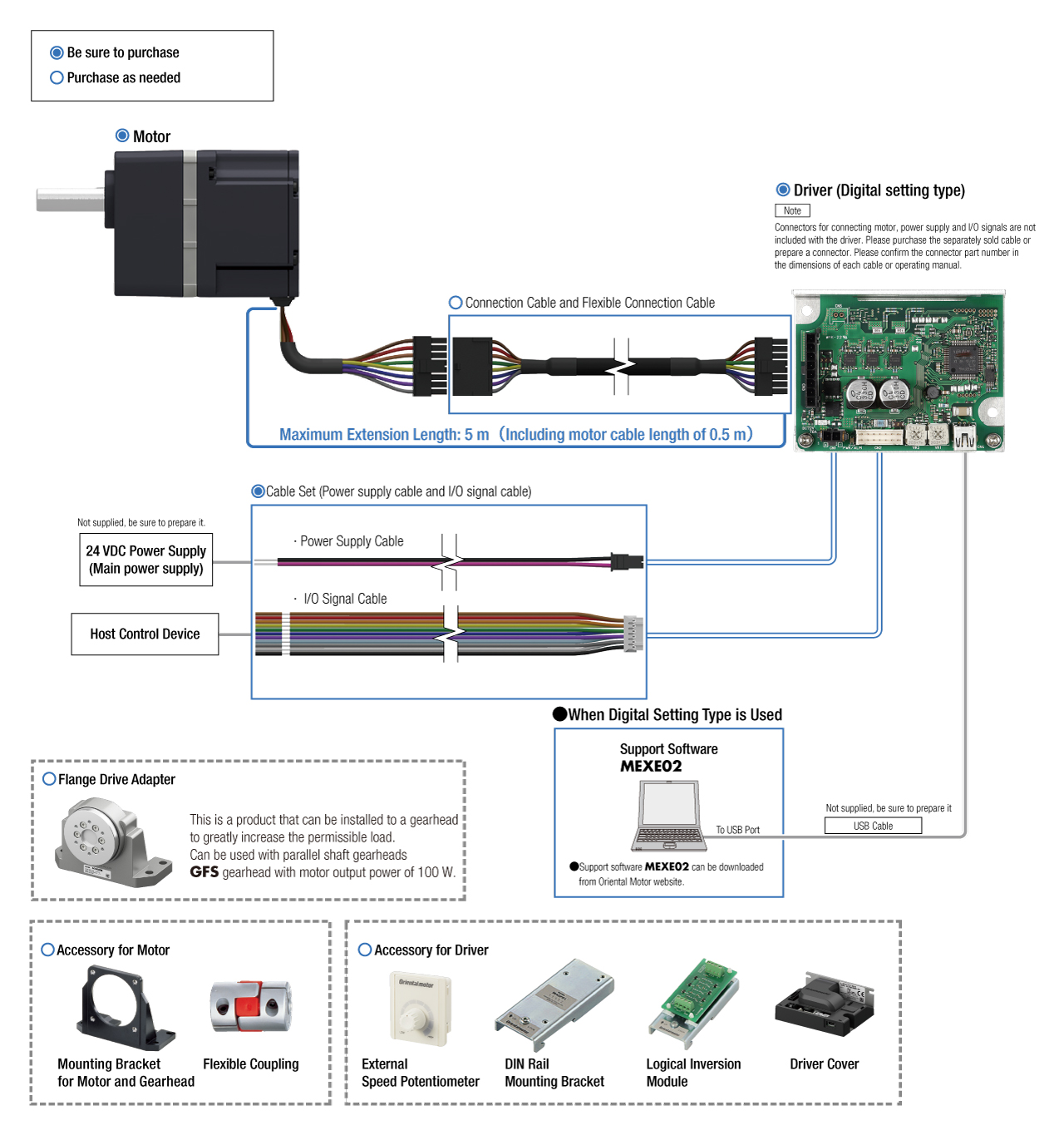
Cables and Accessories
close
close

close
close
close
close