Brushless Motors BLF Series
BLF460A-200
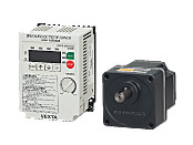
Gearhead / Motor / Control Circuit
This product is currently no longer available for sale
| Product Classification | Product Name | List Price | List Price | Shipping Date |
|---|---|---|---|---|
| Gearhead / Motor / Control Circuit | BLF460A-200 | SGD 779 | USD 623 | Discontinued Product (31.3.2020 discontinued) |
Included
- Motor, Control Circuit, Gearhead, Mounting Screws, Parallel Key, Operating Manual
Specifications
Data Download
Other Specifications
Common Specifications
| Item | Specifications |
|---|---|
| Speed Setting Methods | Select one of the following methods.
|
| Acceleration Time and Deceleration Time (At 3000 r/min) |
0.2~15 seconds (Factory Setting 0.5 seconds) Maximum 8-Speed data by Digital Setting |
| Input Signals (With remote mode setting) |
Photocoupler Input Input Resistance: 3.3 kΩ Internal Power Supply Voltage: 14VDC±10% Connectable External Voltage: 24VDC±10% (only at Source Logic) Sink input (factory default) or source input/2-wire input mode (factory default), or 3-wire input mode CW [START/STOP] input, CCW [RUN/BRAKE] input, STOP-MODE [CW/CCW] input, speed data selection, alarm reset input, external error input [ ] indicates 3-wire input mode |
| Output Signals | Open-collector output 4.5~26.4 VDC max. 10 mA max. (Speed Output: 5 mA min., 10 mA max.) Speed output (30 pulses/rotation), alarm output 1, alarm output 2 |
| Protective Functions* | When the following protective functions are activated, an alarm signal will be output, and the motor will come to a coasting stop. (Instantaneous stop for external abnormality)
|
| Maximum Extension Distance | Motor and driver distance 23.4 m (when an accessory connection cable or extension cable is used) |
| Time Rating | Continuous |
- *The BLF series cannot conduct speed control of the motor in applications in which the motor shaft is turned from the load side, such as gravitational operation.
When a load exceeding the permissible load inertia value is driven, or when gravitational operation is performed, the overvoltage protective function works to bring the motor to a coasting stop.
General Specifications
| Item | Motor | Driver | |
|---|---|---|---|
| Insulation Resistance | 100 MΩ or more when a 500 VDC megger is applied between the windings and the case after continuous operation under normal ambient temperature and humidity. |
After continuous operation at normal ambient temperature and humidity, the measurement value between the power supply terminal and the protective earth terminal and the power supply terminal and the I/O terminal is 100 MΩ min. using a 500 VDC megger. |
|
| Dielectric Strength | No abnormality is observed even with an application of 1.5 kVAC at 50 Hz between the coils and the case for 1 minute after continuous operation at normal ambient temperature and humidity. |
No abnormality is observed even with an application of 1.8 kVAC at 50 Hz between the power supply terminal and the protective earth terminal or 3 kVAC at 50 Hz between the power supply terminal and the signal I/O terminal for 1 minute after continuous operation at normal ambient temperature and humidity. |
|
| Temperature Rise | After continuous operation at normal ambient temperature and humidity, the measured value using the thermocouple method is 50 °Cmax. for the temperature rise of the coils and 40 °C max. *1for the temperature rise on the case surface. |
After continuous operation at normal ambient temperature and humidity, the measurement value of the temperature rise of the heat sink is 50 °C max. using the thermocouple method. |
|
| Operating Environment | Ambient Temperature | 0∼+50°C (Non-freezing) | |
| Ambient Humidity | 85 % max. (Non-condensing) | ||
| Altitude | Up to 1000 m above sea level | ||
| Atmosphere | Cannot be used in special environments such as corrosive gas, no dust, radioactive materials, magnetic fields, or vacuums | ||
| Vibration | Not subject to continuous vibration or excessive shock In conformance with JIS C 60068-2-6, "Sine-wave vibration test method" Frequency Range: 10~55 Hz, Half Amplitude: 0.15 mm, Sweep Direction: 3 directions (X, Y, Z), Number of Sweeps: 20 times |
||
| Storage Conditions*2 | Ambient Temperature | -25~+70°C (Non-freezing) | |
| Ambient Humidity | 85 % max. (Non-condensing) | ||
| Altitude | Up to 3000 m above sea level | ||
| Thermal Class | UL/CSA Standards: 105 (A), EN Standards: 120 (E) | − | |
| Degree of Protection | IP54 (Excluding the installation surface of the round shaft type and connectors) | IP20 | |
- *1
-
Attach round shaft types to a heat sink (Material: aluminum) of one of the following sizes to maintain a motor case surface temperature of 90 °C max.
30 W Type: 115x115 mm, 5 mm thickness
60 W Type: 165x165 mm, 5 mm thickness
120 W Type: 200x200mm, 5mm thickness
200 W Type: 200x200 mm, 5 mm thickness
400 W Type: 250x250 mm, 6 mm thickness - *2
- The value for storage condition applies to short periods such as the period during transport.
Note
- Do not measure insulation resistance or perform a dielectric strength test the motor and driver are connected.
Permissible Radial Load and Permissible Axial Load
Combination type with a parallel shaft gearhead
| Product Name | Gear Ratio | Permissible Radial Load | Permissible Axial Load N |
||
|---|---|---|---|---|---|
| 10 mm From Shaft End N |
20 mm From Shaft End N |
||||
| BLF23■-□S-◇ | 5 | At 80~3000 r/min | 100 | 150 | 40 |
| At 4000 r/min | 90 | 110 | |||
| 10, 15, 20 | At 80~3000 r/min | 150 | 200 | ||
| At 4000 r/min | 130 | 170 | |||
| 30, 50, 100, 200 | At 80~3000 r/min | 200 | 300 | ||
| At 4000 r/min | 180 | 230 | |||
| BLF46■-□S-◇ | 5 | At 80~3000 r/min | 200 | 250 | 100 |
| At 4000 r/min | 180 | 220 | |||
| 10, 15, 20 | At 80~3000 r/min | 300 | 350 | ||
| At 4000 r/min | 270 | 330 | |||
| 30, 50, 100, 200 | At 80~3000 r/min | 450 | 550 | ||
| At 4000 r/min | 420 | 500 | |||
| BLF512■-□S-◇ | 5 | At 80~3000 r/min | 300 | 400 | 150 |
| At 4000 r/min | 230 | 300 | |||
| 10, 15, 20 | At 80~3000 r/min | 400 | 500 | ||
| At 4000 r/min | 370 | 430 | |||
| 30, 50, 100, 200 | At 80~3000 r/min | 500 | 650 | ||
| At 4000 r/min | 450 | 550 | |||
| BLF620■-□S-◇ BLF640S-□S-◇ |
5, 10, 15, 20 | At 80~3000 r/min | 550 | 800 | 200 |
| At 4000 r/min | 500 | 700 | |||
| 30, 50 | At 80~3000 r/min | 1000 | 1250 | 300 | |
| At 4000 r/min | 900 | 1100 | |||
| 100, 200 | At 80~3000 r/min | 1400 | 1700 | 400 | |
| At 4000 r/min | 1200 | 1400 | |||
Combination type with a hollow shaft flat gearhead
| Product Name | Gear Ratio | Permissible Radial Load | Permissible Axial Load N |
||
|---|---|---|---|---|---|
| 10 mm From the Gearhead Mounting Surface N |
20 mm From the Gearhead Mounting Surface N |
||||
| BLF23■-□F-◇ | 5, 10 | At 80~3000 r/min | 450 | 370 | 200 |
| At 4000 r/min | 410 | 330 | |||
| 15, 20, 30, 50, 100, 200 | At 80~3000 r/min | 500 | 400 | ||
| At 4000 r/min | 460 | 370 | |||
| BLF46■-□F-◇ | 5, 10 | At 80~3000 r/min | 800 | 660 | 400 |
| At 4000 r/min | 730 | 600 | |||
| 15, 20, 30, 50, 100, 200 | At 80~3000 r/min | 1200 | 1000 | ||
| At 4000 r/min | 1100 | 910 | |||
| BLF512■-□F-◇ | 5, 10 | At 80~3000 r/min | 900 | 770 | 500 |
| At 4000 r/min | 820 | 700 | |||
| 15, 20 | At 80~3000 r/min | 1300 | 1110 | ||
| At 4000 r/min | 1200 | 1020 | |||
| 30, 50, 100, 200 | At 80~3000 r/min | 1500 | 1280 | ||
| At 4000 r/min | 1400 | 1200 | |||
| BLF620■-□F-◇ BLF640S-□F-◇ |
5*, 10 | At 80~3000 r/min | 1230 | 1070 | 800 |
| At 4000 r/min | 1130 | 990 | |||
| 15, 20 | At 80~3000 r/min | 1680 | 1470 | ||
| At 4000 r/min | 1550 | 1360 | |||
| 30, 50, 100 | At 80~3000 r/min | 2040 | 1780 | ||
| At 4000 r/min | 1900 | 1660 | |||
- *BLF640■-□F-◇ only
Round Shaft Type
| Product Name | Permissible Radial Load | Permissible Axial Load | |
|---|---|---|---|
| 10 mm From Shaft End N |
20 mm From Shaft End N |
||
| BLF23■-A-◇ | 80 | 100 | Half of the motor mass or less |
| BLF46■-A-◇ | 110 | 130 | |
| BLF512■-A-◇ | 150 | 170 | |
| BLF620■-A-◇ BLF640S-A-◇ |
197 | 221 | |
Cables and Accessories
close