Stepper Motor αSTEP ASC Series
ASC66AK-N5
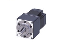
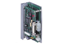
Geared Motor/Control Circuit
This product is currently no longer available for sale
| Product Classification | Product Name | List Price | List Price | Shipping Date |
|---|---|---|---|---|
| Geared Motor / Control Circuit | ASC66AK-N5 | SGD 1,712 | USD 1,370 | Discontinued Product (31.3.2020 discontinued) |
Included
- Motor, Control Circuit, I/O Signal Connector, Power Supply Connector, Parallel Key, Operating Manual
Specifications
Data Download
Other Specifications
Driver Specifications
| speed and positioning control command | Pulse input |
|---|---|
| Maximum Input Pulse Frequency | 250 kHz (at 50 % duty) |
| Protective Function | When the following protective functions are activated, an alarm signal will output, and the motor will come to a coasting stop. Overload protection, overvoltage protection, abnormal speed error protection, overspeed, EEPROM data error, sensor error, system error |
| Input Signals | Photocoupler Input, Input Resistance: 220 Ω, Input current 7~20 mA [CW pulse/CCW pulse (negative logic pulse input), pulse/rotation direction switching (negative logic pulse input), all windings off, alarm clear, resolution select] |
| Output Signals | Photocoupler and open-collector output External Use Conditions: 30 VDC, 15 mA max. (positioning completion, alarms, timing) Transistor and open-collector output, external use conditions 30 VDC, 15 mA max. (Feedback pulse phase A and B) |
General Specifications
| Classification | Motor | Driver | |
|---|---|---|---|
| Insulation Class | Class B (130 °C) [UL/CSA Standards is approved to Class A (105 °C)] | - | |
| Insulation Resistance |
100 MΩ or more when a 500 VDC megger is applied between the following places:
|
100 MΩ or more when a 500 VDC megger is applied between the following places:
|
|
| Dielectric Strength |
Sufficient to withstand the following for 1 minute:
|
Sufficient to withstand the following for 1 minute:
|
|
| Operating Environment (when operating) |
Ambient Temperature | 0~+50 °C (Non-freezing): Standard type TH, PN geared type 0~+40 °C (Non-freezing): Harmonic geared type |
0~+40 °C (Non-freezing) |
| Ambient Humidity | 85 % max. (Non-condensing) | ||
| Atmosphere | No corrosive gases or dust. No exposure to water, oil or other liquids. | ||
| Stop Position Accuracy | ±5 arc minute | - | |
| Shaft Runout | 0.05 T.I.R. (mm) * | - | |
| Concentricity of Installation Pilot to the Shaft |
0.075 T.I.R. (mm) * | - | |
| Perpendicularity of mounting surface to the shaft |
0.075 T.I.R. (mm) * | - | |
- *T.I.R. (Total Indicator Reading): The total dial gauge reading when the measurement section is rotated 1 revolution centered on the reference axis center.
Note
- Do not measure insulation resistance or perform a dielectric strength test while the motor and driver are connected.
Permissible Radial Load and Permissible Axial Load
Unit: N
| Type | Product Name | Gear Ratio | Permissible Radial Load | Permissible Axial Load | ||||
|---|---|---|---|---|---|---|---|---|
| Distance From Shaft End [mm] | ||||||||
| 0 | 5 | 10 | 15 | 20 | ||||
| Standard Type | ASC34AK ASC36AK |
- | 25 | 34 | 52 | - | - | Less than or equal to motor weight |
| ASC46□K | 20 | 25 | 34 | 52 | - | |||
| ASC66□K | 63 | 75 | 95 | 130 | 190 | |||
|
TH Geared Type |
ASC34AK-T■ | 7.2, 10, 20, 30 |
15 | 17 | 20 | 23 | - | 10 |
| ASC46□K-T■ | 3.6, 7.2, 10, 20, 30 |
10 | 14 | 20 | 30 | - | 15 | |
| ASC66□K-T■ | 70 | 80 | 100 | 120 | 150 | 40 | ||
|
PN Geared Type |
ASC34AK-N■ | 5, 7.2, 10 | 45 | 60 | 80 | 100 | - | 20 |
| ASC46□K-N■ | 7.2, 10 | 100 | 120 | 150 | 190 | - | 100 | |
| ASC66□K-N■ | 5 | 200 | 220 | 250 | 280 | 320 | ||
| 7.2, 10 | 250 | 270 | 300 | 340 | 390 | |||
| 25, 36, 50 | 330 | 360 | 400 | 450 | 520 | |||
| Harmonic Geared Type |
ASC34AK-H ■ | 50, 100 | 140 | 160 | 200 | 240 | - | |
| ASC46□K-H ■ | 180 | 220 | 270 | 360 | 510 | 220 | ||
| ASC66□K-H ■ | 320 | 370 | 440 | 550 | 720 | 450 | ||
- *Either A or M indicating the shape is specified where the box □ is located in the product name.
A number indicating the gear ratio is specified where the box ■ is located in the product name.
System Configuration
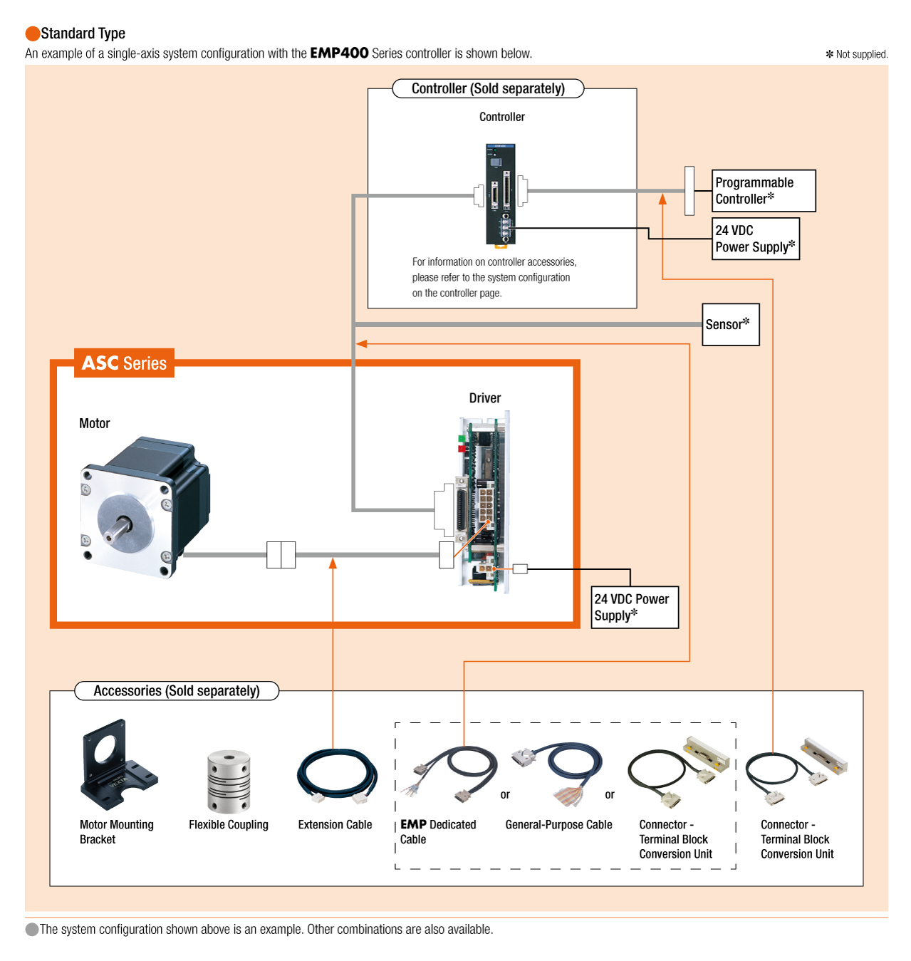
Cables and Accessories
close