Stepper Motor αSTEP AS Series Built-In Controller Type
AS98MSED-N5
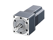
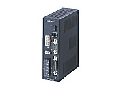
Geared Motor/Control Circuit
This product is currently no longer available for sale
| Product Classification | Product Name | List Price | List Price | Shipping Date |
|---|---|---|---|---|
| Geared Motor / Control Circuit | AS98MSED-N5 | SGD 3,486 | USD 2,789 | Discontinued Product (31.3.2019 discontinued) |
Included
- Motor, Control Circuit, Mounting Bracket for Control Circuit (with Screws), I/O Signal Connector, Parallel Key, Varistor, Operating Manual
Specifications
Data Download
Other Specifications
Driver Specifications
| Pulse Input Package | Built-in Controller Package | |
|---|---|---|
| Speed and Position Control Command | Pulse input | Stored data |
| Maximum Input Pulse Frequency | 250 kHz (at 50 % duty) | − |
| Protective Function | When the following protective functions are activated, an alarm signal will output, and the motor will come to a coasting stop. | |
| Overheat protection, overload protection, overvoltage protection, speed error protection, overcurrent protection, overspeed, EEPROM data error, sensor error, system error |
Overheat protection, overload protection, overvoltage protection, overcurrent protection, overspeed, EEPROM data error, sensor error, excessive position deviation, rotor rotation error at initiation, E-STOP detection, limit sensor logic error, limit sensor reverse connection, HOME operation error, hard limit detection, out of software limit range, operation data invalid |
|
| Input Signals | Photocoupler Input Input Resistance: 220 Ω Input current 7 ~ 20 mA [CW pulse, CCW pulse (negative logic pulse input), pulse and rotation direction (negative logic pulse input), current off, Alarm clear, resolution switching] |
Photocoupler Input Input Resistance: 4.7 kΩ 24 VDC±10 % |
| Output Signals | Photocoupler and Open-Collector Output External Operating Conditions: 30 V DC, 15 mA max. (Positioning complete, alarm) Transistor and open-collector output External Operating Conditions: 30 V DC, 15 mA max. (Timing, feedback pulses phase A and B) Line driver output 26C31 equivalent (Timing, feedback pulses phase A and B) |
Photocoupler and Open-Collector Output External Operating Conditions: 30 V DC, 15 mA max. |
| Data-select positioning | − | 61 data maximum (stored in EEPROM) Data-select positioning |
| Positioning Control | − |
|
| Operation Mode | − |
|
| Return-to-mechanical home operation | − | Perform return-to-home operation from the entire range using mechanism detection signal (+LS, -LS, HOMELS). |
| Other Functions | − |
|
- *The acceleration rate and deceleration rate can be set separately.
General Specifications
| Classification | Motor | Driver | |
|---|---|---|---|
| Insulation Class | Class B (130 °C) [UL/CSA Standards is approved to Class A (105 °C)] | − | |
| Insulation Resistance |
100 MΩ or more when a 500 VDC megger is applied between the following places:
|
100 MΩ or more when a 500 VDC megger is applied between the following places:
|
|
| Dielectric Strength |
Sufficient to withstand the following for 1 minute:
|
Sufficient to withstand the following for 1 minute:
|
|
| Operating Environment (when operating) |
Ambient Temperature | 0 ~ +50 °C (Non-freezing): Standard type TH, PL, PN geared type 0 ~ 40 ˚C (Non-freezing): Harmonic geared type |
0 ~ +50 °C (Non-freezing): Pulse input package 0 ~ +40 °C (Non-freezing): Built-in controller package |
| Ambient Humidity | 85 % max. (Non-condensing) | ||
| Atmosphere | No corrosive gases or dust. No exposure to water, oil or other liquids. (Standard Type Motor with Metal Connector: No corrosive gases. No exposure to oil) |
||
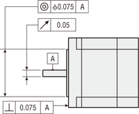
| Stop Position Accuracy | ±5 arcmin | − | |
| Shaft Runout | 0.05 T.I.R. (mm)* | − | |
| Concentricity of Installation Pilot to the Shaft | 0.075 T.I.R. (mm)* | − | |
| Perpendicularity of mounting surface to the shaft | 0.075 T.I.R. (mm)* | − | |
- *T.I.R. (Total Indicator Reading): The total dial gauge reading when the measurement section is rotated 1 revolution centered on the reference axis center.
Note
- Do not measure insulation resistance or perform a dielectric strength test while the motor and driver are connected.
Permissible Radial Load and Permissible Axial Load
| Type | Product Name | Gear Ratio | Permissible Radial Load | Permissible Axial Load | |||||
|---|---|---|---|---|---|---|---|---|---|
| Distance From Shaft End [mm] | |||||||||
| Pulse input | Built-In Controller | 0 | 5 | 10 | 15 | 20 | |||
| Standard Type Standard Type With Metal Connector |
AS46□A | AS46□AD | − | 20 | 25 | 34 | 52 | − | Less than or equal to motor weight |
| AS66□◆E AS66A◆T | AS66□◆ED | 63 | 75 | 95 | 130 | 190 | |||
| AS69□◆E AS69A◆T | AS69□◆ED | ||||||||
| AS98□◆E AS98A◆T | AS98□◆ED | 260 | 290 | 340 | 390 | 480 | |||
| AS911A◆E AS911A◆T | AS911A◆ED | ||||||||
| TH Geared Type | AS46□A-T■ | AS46□AD-T■ | 3.6, 7.2, 10, 20, 30 |
10 | 14 | 20 | 30 | − | 15 |
| AS66□◆E-T■ | AS66□◆ED-T■ | 70 | 80 | 100 | 120 | 150 | 40 | ||
| AS98□◆E-T■ | AS98□◆ED-T■ | 220 | 250 | 300 | 350 | 400 | 100 | ||
| PL Geared Type | AS46□A-P■ | AS46□AD-P■ | 7.2, 10 | 73 | 84 | 100 | 123 | − | 50 |
| 36, 50 | 109 | 127 | 150 | 184 | − | ||||
| AS66□◆E-P■ | AS66□◆ED-P■ | 5 | 200 | 220 | 250 | 280 | 320 | 100 | |
| 7.2, 10 | 250 | 270 | 300 | 340 | 390 | ||||
| 25, 36, 50 | 330 | 360 | 400 | 450 | 520 | ||||
| AS98□◆E-P■ | AS98□◆ED-P■ | 5, 7.2, 10 | 480 | 540 | 600 | 680 | 790 | 300 | |
| 25 | 850 | 940 | 1050 | 1190 | 1380 | ||||
| 36 | 930 | 1030 | 1150 | 1310 | 1520 | ||||
| 50 | 1050 | 1160 | 1300 | 1480 | 1710 | ||||
| PN Geared Type | AS46□A-N■ | AS46□AD-N■ | 7.2, 10 | 100 | 120 | 150 | 190 | − | 100 |
| AS66□◆E-N■ | AS66□◆ED-N■ | 5 | 200 | 220 | 250 | 280 | 320 | ||
| 7.2, 10 | 250 | 270 | 300 | 340 | 390 | ||||
| 25, 36, 50 | 330 | 360 | 400 | 450 | 520 | ||||
| AS98□◆E-N■ | AS98□◆ED-N■ | 5 | 480 | 520 | 550 | 580 | 620 | 300 | |
| 7.2, 10 | 480 | 540 | 600 | 680 | 790 | ||||
| 25 | 850 | 940 | 1050 | 1110 | 1190 | ||||
| 36 | 930 | 1030 | 1150 | 1220 | 1300 | ||||
| 50 | 1050 | 1160 | 1300 | 1380 | 1490 | ||||
| Harmonic Geared Type |
AS46□A2-H■ | AS46□AD2-H■ | 50, 100 | 180 | 220 | 270 | 360 | 510 | 220 |
| AS66□◆E-H■ | AS66□◆ED-H■ | 320 | 370 | 440 | 550 | 720 | 450 | ||
| AS98□◆E-H■ | AS98□◆ED-H■ | 1090 | 1150 | 1230 | 1310 | 1410 | 1300 | ||
- Either A or M indicating the power supply input is specified where the box ■ is located in the product name.
Either A, C, or S indicating the power supply input is specified where the box ■ is located in the product name.
A number indicating the gear ratio is specified where the box ■ is located in the product name.
System Configuration
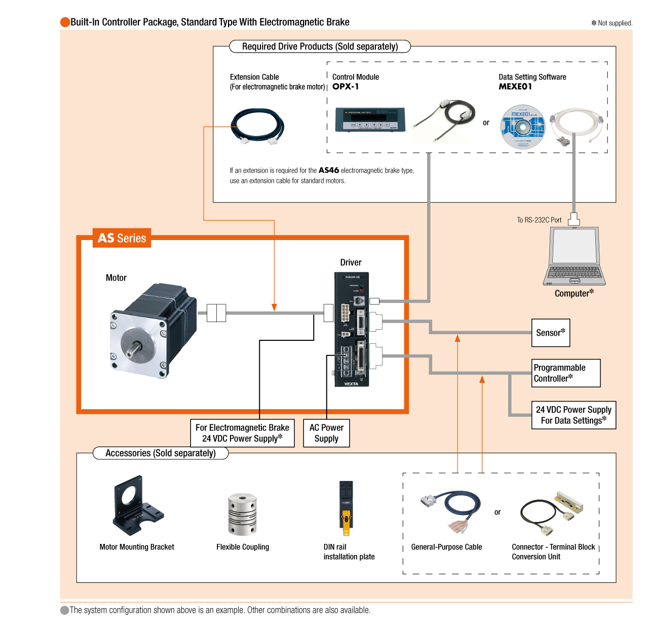
Cables and Accessories
close