Stepper Motor αSTEP AS Series CC-Link Ver.1.1 Compatible
AS46MACC-T10
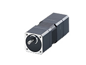
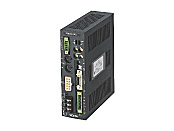
Geared Motor/Control Circuit
This product is currently no longer available for sale
| Product Classification | Product Name | List Price | List Price | Shipping Date |
|---|---|---|---|---|
| Geared Motor / Control Circuit | AS46MACC-T10 | SGD 3,090 | USD 2,472 | Discontinued Product (31.3.2019 discontinued) |
Included
- Motor, Control Circuit, Mounting Bracket for Control Circuit (with Screws), CC-Link-Compatible Connector, Power Supply for CC-Link-Compatible Communication, Sensor and User I/O Connector, Control Power Supply Input Terminal, Emergency Stop Output Terminal, Electromagnetic Brake Output Terminal, Varistor, Operating Manual
Specifications
Other Specifications
Driver Specifications
| Input Signals | Photocoupler Input Input Resistance: 4.7 kΩ 24 VDC±10 % |
|---|---|
| Output Signals | Photocoupler and Open-Collector Output External operating conditions: 30 V DC, 15 mA max. |
| Data-select positioning | 63 data maximum (stored in EEPROM) Data-select positioning |
| Positioning Control |
|
| Operation Mode |
|
| Return-to-mechanical home operation | Perform return-to-home operation from the entire range using mechanism detection signal (+LS, -LS, HOMELS). |
| Protective Function | Overheat protection, overload protection, overspeed, overvoltage protection, main power supply interruption detection, excessive position deviation, overcurrent protection, EMG input detection, insufficient battery voltage for ABS*2, absolute position loss*2, LS logic error, LS reverse connection error, return-to-home error, HOMELS not detected error, TIM.,SLIT not detected error, LS detection error, software limit detection, HOME offset error, operation data error, network error, sensor error, rotation during initialization, subsystem error, non-volatile memory error |
- *1
- The acceleration rate and deceleration rate can be set separately.
- *2
- Insufficient battery voltage for ABS and loss of absolute position will occur only when using the absolute specification.
Battery Specifications
| Battery Types | cylindrical sealed nickel-cadmium storage cell |
|---|---|
| nominal voltage | 2.4V |
| Rated Capacity | 2000 mAh |
| Mass | 0.18 kg |
| lifetime | Approx. 4 years*1 |
| Charge Time | 48 hours*1 |
| Data Retention Period*1 *2 | 15 days |
| Operating Ambient Temperature | 0 ~ +40 °C (Non-freezing) |
| operating ambient humidity | 20~85 %RH (non-condensing) |
| protective circuit | Fuse |
| Storage Temperature | -20~+45 °C (up to 3 months), -20~+35 °C (over 3 months) |
- *1
- When the ambient temperature at motor standstill is 20 °C
- *2
- When the battery is fully charged, and the power supply is switched OFF.
CC-Link Communication Specifications
| Communication Protocol | CC-Link Ver.1.10 |
|---|---|
| Station Type | Remote device station |
| Number of Occupied Stations | 1 station occupancy/2 stations occupancy switch |
| Transmission Rate | 156 kbps/625 kbps/2.5 Mbps/5 Mbps/10 Mbps |
| Maximum Transmission Distance | Varies depending on transmission rate |
| Maximum Number of Connected Units | 42 units The maximum number of connected units depends on the configuration of the CC-Link system used. For details, conduct confirmation of the specifications of the CC-Link system master (or local) device. |
| Communication Cable | CC-Link dedicated cable |
| connector | Phoenix Contact Corporation MVSTBW2,5/5-STF-5,08AU |
Driver function
| Language Settings | Japanese/English |
|---|---|
| Positioning Operation Method (Operation mode can be set for 63 data from No. 01 - 63) |
|
| Positioning Operation |
|
| Push-Motion Operation | Push Current: 0~50 % |
| Continuous Operation | When Data No. 00 is selected, operation is performed at the common operating speed. When a Data No. is selected, operation is performed at the selected operating speed. |
| Return-To-Home Operation |
Starting Direction:
+ side (CW) / - side (CCW)
Home Offset:
−8,388,608 - +8,388,607 step
Homing Method:
3 sensors / 2 sensors / push operation
Return-to-home starting speed:
1 ~ 500,000 Hz
500 Hz max. when in push mode (when gear ratio is at initial value) Operating Speed of Home-Seeking::
1 ~ 500,000 Hz
500 Hz max. when in push mode (when gear ratio is at initial value) |
| Positioning Data | Number of Data Points: 63 points (No. 01~63) |
| travel amount | Setting Range: -8,388,608 - +8,388,607 step Setting Unit: 1 step |
| starting speed | Setting Range: 1 ~ 500,000 Hz Setting Unit: 1 Hz |
| Common Operating Speed | Setting Range: 1 ~ 500,000 Hz Setting Unit: 1 Hz |
| Acceleration Rate, Deceleration Rate | Setting Range: 0.01 ~ 1000.00 ms/kHz Setting Unit: 0.01 ms/kHz |
| Operating speed | Setting Range: 1 ~ 500,000 Hz Setting Unit: 1 Hz |
| Operating Current | Setting Range: 0 ~ 100 %. Setting Unit: 1 %. |
| Stop current | Setting Range: 0 ~ 50 %. Setting Unit: 1 %. |
General Specifications
Values are after rated operation at normal ambient temperature and humidity.
| Classification | Motor | Driver | |
|---|---|---|---|
| Insulation Class | Class B (130 °C) [UL/CSA Standards is approved to Class A (105 °C)] | − | |
| Insulation Resistance |
100 MΩ or more when a 500 VDC megger is applied between the following places:
|
100 MΩ or more when a 500 VDC megger is applied between the following places:
|
|
| Dielectric Strength |
Sufficient to withstand the following for 1 minute:
|
Sufficient to withstand the following for 1 minute:
|
|
| Operating Environment (when operating) |
Ambient Temperature | 0~+40 °C (Non-freezing): Harmonic geared type 0~+50 °C (Non-freezing): Standard type, TH, PL, PN geared type |
0~+40 °C (Non-freezing) |
| Ambient Humidity | 85 % max. (Non-condensing) | ||
| Atmosphere | No corrosive gases or dust. No exposure to water, oil or other liquids. (Standard Type Degree of Protection IP65 Rating: No corrosive gases) | ||
| Stop Position Accuracy | ±5 arc minute | − | |
| Shaft Runout | 0.05 T.I.R. (mm) * | − | |
| Concentricity of Installation Pilot to the Shaft | 0.075 T.I.R. (mm) * | − | |
| Perpendicularity of mounting surface to the shaft | 0.075 T.I.R. (mm) * | − | |
- *T.I.R. (Total Indicator Reading): The total dial gauge reading when the measurement section is rotated 1 revolution centered on the reference axis center.
Note
- Do not measure insulation resistance or perform a dielectric strength test while the motor and driver are connected.
Permissible Radial Load and Permissible Axial Load
Unit: N
| Type | Product Name | Gear Ratio | Permissible Radial Load | Permissible Axial Load | ||||
|---|---|---|---|---|---|---|---|---|
| Distance From Shaft End [mm] | ||||||||
| 0 | 5 | 10 | 15 | 20 | ||||
| Standard Type Standard Type Degree of Protection IP65 Rating |
AS46□ACC | − | 20 | 25 | 34 | 52 | - | Less than or equal to motor weight |
| AS66□■ECC AS69□■ECC |
63 | 75 | 95 | 130 | 190 | |||
| AS66A■TCC AS69A■TCC |
63 | 75 | 95 | 130 | 190 | |||
| AS98□■ECC AS911A ■ECC |
260 | 290 | 340 | 390 | 480 | |||
| AS98A■TCC AS911A■TCC |
260 | 290 | 340 | 390 | 480 | |||
| TH Geared Type | AS46□ACC-T◇ | 3.6, 7.2, 10, 20, 30 |
10 | 14 | 20 | 30 | − | 15 |
| AS66□■ECC-T◇ | 70 | 80 | 100 | 120 | 150 | 40 | ||
| AS66□■ECC-T◇ | 220 | 250 | 300 | 350 | 400 | 100 | ||
| PL Geared Type | AS46□ACC-P◇ | 7.2, 10 | 73 | 84 | 100 | 123 | − | 50 |
| AS46□ACC-P◇ | 36, 50 | 109 | 127 | 150 | 184 | − | ||
| AS66□■ECC-P5 | 5 | 200 | 220 | 250 | 280 | 320 | 100 | |
| AS66□■ECC-P◇ | 7.2, 10 | 250 | 270 | 300 | 340 | 390 | ||
| AS66□■ECC-P◇ | 25, 36, 50 | 330 | 360 | 400 | 450 | 520 | ||
| AS98□■ECC-P◇ | 5, 7.2, 10 | 480 | 540 | 600 | 680 | 790 | 300 | |
| AS98□■ECC-P25 | 25 | 850 | 940 | 1050 | 1190 | 1380 | ||
| AS98□■ECC-P36 | 36 | 930 | 1030 | 1150 | 1310 | 1520 | ||
| AS98□■ECC-P50 | 50 | 1050 | 1160 | 1300 | 1480 | 1710 | ||
| PN Geared Type | AS46□ACC-N◇ | 7.2, 10 | 100 | 120 | 150 | 190 | − | 100 |
| AS66□■ECC-N5 | 5 | 200 | 220 | 250 | 280 | 320 | ||
| AS66□■ECC-N◇ | 7.2, 10 | 250 | 270 | 300 | 340 | 390 | ||
| AS66□■ECC-N◇ | 25, 36, 50 | 330 | 360 | 400 | 450 | 520 | ||
| AS98□■ECC-N5 | 5 | 480 | 520 | 550 | 580 | 620 | 300 | |
| AS98□■ECC-N◇ | 7.2, 10 | 480 | 540 | 600 | 680 | 790 | ||
| AS98□■ECC-N25 | 25 | 850 | 940 | 1050 | 1110 | 1190 | ||
| AS98□■ECC-N36 | 36 | 930 | 1030 | 1150 | 1220 | 1300 | ||
| AS98□■ECC-N50 | 50 | 1050 | 1160 | 1300 | 1380 | 1490 | ||
| Harmonic Geared Type | AS46□ACC2-H◇ | 50, 100 | 180 | 220 | 270 | 360 | 510 | 220 |
| AS66□■ECC-H◇ | 320 | 370 | 440 | 550 | 720 | 450 | ||
| AS98□■ECC-H◇ | 1090 | 1150 | 1230 | 1310 | 1410 | 1300 | ||
- *Either A (standard) or M (equipped with electromagnetic brake) is specified where the box □ is located in the product name.
Either A or C indicating the power supply input is specified where the box ■ is located in the product name.
A number indicating the gear ratio is specified where the box ◇ is located in the product name.
System Configuration
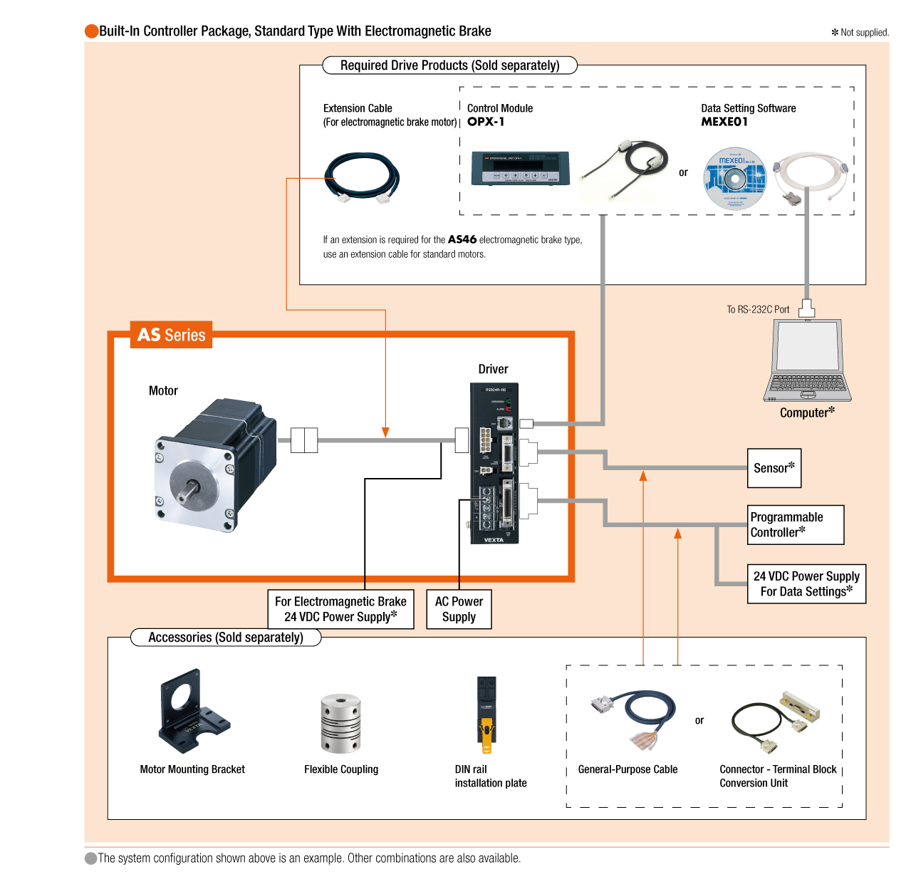
Cables and Accessories
close